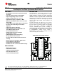
TPS40322 www.ti.com SLUSAF8D – JUNE 2011 – REVISED JANUARY 2014 Dual Output or Two-Phase Synchronous Buck Controller FEATURES DESCRIPTION • The TPS40322 is a dual-output, synchronous buck controller. It can also be configured as a singleoutput, two-phase controller. The 180° out-of-phase operation reduces the input current ripple and extends the input capacitor lifetime.
TPS40322 SLUSAF8D – JUNE 2011 – REVISED JANUARY 2014 www.ti.com These devices have limited built-in ESD protection. The leads should be shorted together or the device placed in conductive foam during storage or handling to prevent electrostatic damage to the MOS gates.
TPS40322 www.ti.com SLUSAF8D – JUNE 2011 – REVISED JANUARY 2014 THERMAL INFORMATION TPS40322 THERMAL METRIC (1) QFN UNITS 32 PINS Junction-to-ambient thermal resistance (2) θJA (3) 37.3 θJCtop Junction-to-case (top) thermal resistance θJB Junction-to-board thermal resistance (4) 10.0 ψJT Junction-to-top characterization parameter (5) 0.4 ψJB Junction-to-board characterization parameter (6) 9.9 θJCbot Junction-to-case (bottom) thermal resistance (7) 2.7 (1) (2) (3) (4) (5) (6) (7) 28.
TPS40322 SLUSAF8D – JUNE 2011 – REVISED JANUARY 2014 www.ti.com ELECTRICAL CHARACTERISTICS TJ = –40°C to 125°C, VVDD = 12 V, RRT = 40 kΩ, fSW = 500 kHz (unless otherwise noted), PARAMETER TEST CONDITIONS MIN TYP MAX UNITS 20 V 200 250 µA 6 8 mA 1.21 1.24 1.27 V 13 15 17 μA 6.2 6.5 6.8 V 50 100 mV INPUT SUPPLY VDD Input voltage range IDDSDN Shutdown VENx/SSx = 0 V 3 IDDQ Quiescent, non-switching VFB = 0.
TPS40322 www.ti.com SLUSAF8D – JUNE 2011 – REVISED JANUARY 2014 ELECTRICAL CHARACTERISTICS (continued) TJ = –40°C to 125°C, VVDD = 12 V, RRT = 40 kΩ, fSW = 500 kHz (unless otherwise noted), PARAMETER TEST CONDITIONS MIN TYP MAX UNITS V ENABLE/SOFT START VIH High-level input voltage 0.55 0.70 1.00 VIL Low-level input voltage 0.23 0.26 0.30 V ISS Soft-start source current 8 10 12 μA VSS Soft-start voltage level 0.
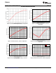
TPS40322 SLUSAF8D – JUNE 2011 – REVISED JANUARY 2014 www.ti.com TYPICAL CHARACTERISTICS UVLO Hysteresis Current (µA) 15.8 15.6 15.4 15.2 15.0 14.8 14.6 14.4 −40 −25 −10 Figure 1. UVLO Turn-On Voltage vs. Junction Temperature 10.9 10.8 10.7 10.6 10.5 5 20 35 50 65 80 Junction Temperature (°C) 95 110 125 Non−Switching Quiescent Current (mA) Soft−Start Current (µA) 11.0 10.4 6.35 6.30 6.25 6.20 6.15 6.10 6.05 6.00 5 20 35 50 65 80 Junction Temperature (°C) 95 110 125 Figure 4.
TPS40322 www.ti.com SLUSAF8D – JUNE 2011 – REVISED JANUARY 2014 780 290 760 High Level Input Voltage (mV) Low Level Input Voltage (mV) TYPICAL CHARACTERISTICS (continued) 300 280 270 260 250 240 230 −40 −25 −10 5 20 35 50 65 80 Junction Temperature (°C) 95 680 660 640 10.3 10.2 10.1 10.0 9.9 95 110 125 0.8 0.6 0.4 0.2 0.0 −0.2 −0.4 −40 −25 −10 Switching Frequency (kHz) 105.8 1.0000 0.9999 0.9998 0.9997 0.9996 0.9995 95 110 125 G001 105.6 105.4 105.2 105.0 104.8 104.6 104.4 104.
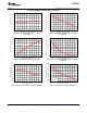
TPS40322 SLUSAF8D – JUNE 2011 – REVISED JANUARY 2014 www.ti.com TYPICAL CHARACTERISTICS (continued) 520 Switching Frequency (kHz) Switching Frequency (kHz) 1040 1035 1030 1025 1020 5 20 35 50 65 80 Junction Temperature (°C) 95 110 125 Figure 13. Frequency vs.
TPS40322 www.ti.
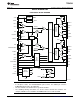
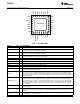
TPS40322 ILIM1 CS1– CS1+ PG1 VDD 32 31 30 29 28 27 26 BOOT1 UVLO www.ti.com PHSET SLUSAF8D – JUNE 2011 – REVISED JANUARY 2014 SYNC 1 25 24 RT 2 23 SW1 EN1/SS1 3 22 LDRV1 FB1 4 21 PGND1 COMP1 5 20 BP6 AGND 6 19 PGND2 7 18 LDRV2 8 17 SW2 9 10 11 12 13 14 15 16 EN2/SS2/GSNS ILIM2/VSNS CS2– CS2+ PG2 BOOT2 HDRV2 FB2 DIFFO COMP2 TPS40322RHB HDRV1 Table 1. PIN FUNCTIONS NAME PIN I/O AGND 6 – Low noise ground connection to the controller.
TPS40322 www.ti.com SLUSAF8D – JUNE 2011 – REVISED JANUARY 2014 Table 1. PIN FUNCTIONS (continued) NAME PIN I/O DESCRIPTION HDRV2 16 O Bootstrapped gate drive output for the high-side N-channel MOSFET for CH2. A 2-Ω resistor is recommended for a noisy environment. ILIM1 30 I Used to set the overcurrent limit for CH1 with 10 μA of current flowing through a resistor from this pin to AGND.
TPS40322 SLUSAF8D – JUNE 2011 – REVISED JANUARY 2014 www.ti.com FUNCTIONAL DESCRIPTION General Description/Control Architecture The TPS40322 is a flexible synchronous buck controller. It can be used as a dual-output controller, or as a twophase, single-output controller. It operates with a wide input range from 3 V to 20 V and can generate an accurate regulated output as low as 600 mV. In dual output mode, voltage mode control with input feed-forward architecture is implemented.
TPS40322 www.ti.com SLUSAF8D – JUNE 2011 – REVISED JANUARY 2014 Input Voltage Feed-Forward The TPS40322 uses input voltage feed-forward to maintain a constant power stage gain as the input voltage varies and provides very good response to input voltage transient disturbances.
TPS40322 SLUSAF8D – JUNE 2011 – REVISED JANUARY 2014 www.ti.com Overcurrent Protection The TPS40322 has dedicated ILIM pins for each channel for use when operating in dual-output mode. When operating in two-phase mode, both channels share the same overcurrent level set by ILIM1. The overcurrent level is set with a resistor connected from the ILIMx pin to analog ground.
TPS40322 www.ti.com SLUSAF8D – JUNE 2011 – REVISED JANUARY 2014 Two-Phase Mode, Remote Sense Amplifier, and Current Sharing Loop The TPS40322 can be configured to operate in single-output, two-phase mode for high-current applications. With proper selection of the external MOSFETs, this device can support up to 50-A of load current in a two-phase configuration. As shown in Figure 18, to configure the TPS40322 for two-phase mode, FB2 is tied to BP6.
TPS40322 SLUSAF8D – JUNE 2011 – REVISED JANUARY 2014 www.ti.com L1 IO1 DCR L VOUT SW1 R1 CS1+ + C1 ISNS1 CS1- + FB1 PWM1 RAMP1 VREF + S COMP1 ISHARE COMP2 BP6 VREF FB2 + S + CS2– PWM2 RAMP2 ISNS2 C2 CS2+ + R2 SW2 IO2 DCR L UDG-11115 L2 Figure 19.
TPS40322 www.ti.com SLUSAF8D – JUNE 2011 – REVISED JANUARY 2014 Startup and Shutdown Startup Sequence When the ENx/SSx pin is pulled below 0.3 V, the respective channel is disabled. When ENx/SSx is released, the controller starts automatically and an internal 40-µA current source begins to charge the external soft-start capacitor. When the voltage across the soft-start capacitor is over 0.7 V, the internal BP regulator is enabled. The ENx/SSx voltage is clamped to 1.
TPS40322 SLUSAF8D – JUNE 2011 – REVISED JANUARY 2014 www.ti.com Shutdown During the shutdown sequence, BP6 is controlled by ENx/SSx. If both of ENx/SSx pins are pulled low, BP6 is turned off regardless of the input voltage remaining higher than the programmed UVLO threshold. Switching Frequency and Master/Slave Synchronization The switching frequency is set by the value of the resistor connected from the RT pin to AGND. The RT resistor value is calculated in Equation 5.
TPS40322 www.ti.com SLUSAF8D – JUNE 2011 – REVISED JANUARY 2014 Overvoltage and Undervoltage Fault Protection The TPS40322 has output overvoltage protection and undervoltage protection capability. The comparators that regulate the overvoltage and undervoltage conditions use the FBx pin as the output sensing point so the filtering effect of the compensation network connected from COMPx to FBx has an effect on the speed of detection.
TPS40322 SLUSAF8D – JUNE 2011 – REVISED JANUARY 2014 www.ti.com LAYOUT CONSIDERATIONS Power Stage A synchronous BUCK power stage has two primary current loops. The input current loop carries high AC discontinuous current while the output current loop carries high DC continuous current. The input current loop includes the input capacitors, the main switching MOSFET, the inductor, the output capacitors and the ground path back to the input capacitors.
TPS40322 www.ti.com SLUSAF8D – JUNE 2011 – REVISED JANUARY 2014 TPS40322 Design Example 1 Dual-Output Configuration from 12-V Nominal to 1.2-V and 1.8-V DC-to-DC Converter Using the TPS40322 The following example illustrates the design process and component selection for a dual output synchronous buck converter using the TPS40322 controller. The design goal parameters are listed in Table 3. Table 3.
TPS40322 SLUSAF8D – JUNE 2011 – REVISED JANUARY 2014 www.ti.com The RMS current through the inductor is approximated by the equation: 2 (I ( ) ) + ( IL1(rms ) = 1 ´I 12 RIPPLE1 L1 avg 2 ) = 2 (IOUT1 )2 + (112 ´ IRIPPLE1 ) 2 = 102 + (112 ´ 2.5 ) = 10.026 A (9) Output Capacitor Selection (C10 through C16) The selection of the output capacitor is typically driven by the output transient response requirement.
TPS40322 www.ti.com SLUSAF8D – JUNE 2011 – REVISED JANUARY 2014 A 744314110 from Wurth-Midcom with 1.1-µH zero current inductance is selected. Inductance for this part is 0.88-µH at 10 A bias. This 15-A, 3.15 mΩ inductor exceeds the minimum inductor ratings in a 7 mm x 7 mm package. Input Capacitor Selection (C3 through C6) The input voltage ripple is divided between the capacitance and ESR of the input capacitor. For this design VRIPPLE(cap) = 200 mV and VRIPPLE(esr) = 50 mV.
TPS40322 SLUSAF8D – JUNE 2011 – REVISED JANUARY 2014 www.ti.com The current limit resistor is calculated using the minimum ILIM programming current, IILIM(min), the maximum current sense amplifier gain, ACS, and assuming a current sense amplifier minimum input offset voltage, VOS(min) equal to –3 mV. (V OC RLIM = ) - VOS(min ) ´ A CS IILIM(min ) = (51.05mV - (-3mV )) ´ 15 V 9.5 mA V = 85.3kW @ 86.
TPS40322 www.ti.com SLUSAF8D – JUNE 2011 – REVISED JANUARY 2014 Power Good (PG1, PG2 Pins) PG1 and PG2 can each be pulled up to BP6 through a 100-kΩ resistor, or remain not-connected. For sequencing the start-up of output 1 before output 2, connect PG1 to EN2/SS2; for sequencing the startup of output 2 before output 1, connect PG2 to EN1/SS1. Phase Set (PHSET Pin) The PHSET pin can be connected to ground or connected to the BP6 pin.
TPS40322 + + + + www.ti.com + SLUSAF8D – JUNE 2011 – REVISED JANUARY 2014 Figure 23.
TPS40322 www.ti.com SLUSAF8D – JUNE 2011 – REVISED JANUARY 2014 Typical Performance Characteristics 95 95 VOUT = 1.2 V 90 85 80 80 Efficiency (%) 85 70 65 60 50 0 1 2 3 4 5 6 7 Output Current (A) 8 9 65 55 50 10 VIN = 8 V VIN = 12 V VIN = 15 V VOUT = 1.8 V 0 1 2 G001 Figure 24. Efficiency vs Load Current (8 V to 15 V to 1.
TPS40322 SLUSAF8D – JUNE 2011 – REVISED JANUARY 2014 www.ti.com Figure 28 shows the switching waveform, VIN = 12 V, IOUT1 = IOUT2 = 10 A, Ch.1 = HDRV1, Ch.2 = LDRV1, Ch.3 = VOUT1 ripple. The high-frequency noise is caused by parasitic inductive and capacitive elements interacting with the high energy, rapidly switching power elements resulting in ringing at the transition points. Capacitive filtering at the load input will successfully attenuate these noise spikes. Figure 28.
TPS40322 www.ti.com SLUSAF8D – JUNE 2011 – REVISED JANUARY 2014 Table 5. Design Example 1, Dual-Output List of Materials REFERENCE DESIGNATOR QTY DESCRIPTION PART NUMBER MFR C1 1 Capacitor, Aluminum, 100 µF, 35 V, ±20%, 0.328 x 0.328 inch EEV-FK1V101GP Panasonic - ECG C2, C7, C20, C26, C39 5 Capacitor, Ceramic, 0.1 µF, 50 V, X7R, ±10%, 0603 Std Std C3, C35 2 Capacitor, Ceramic, 0.1 µF, 25 V, X5R, ±10%, 0402 Std Std C4, C36 2 Capacitor, Ceramic, 1.
TPS40322 SLUSAF8D – JUNE 2011 – REVISED JANUARY 2014 www.ti.com TPS40322 Design Example 2 Two-Phase, Single Output Configuration from 12-V nominal to 1.2-V DC-to-DC Converter Using the TPS40322 The following example shows the schematic, waveforms, and components for a two-phase, single output synchronous buck converter using the TPS40322 controller. The design goal parameters are given in Table 6. Table 6. TPS40322 Design Example Specification PARAMETER TEST CONDITION MIN NOM 4.
TPS40322 www.ti.com SLUSAF8D – JUNE 2011 – REVISED JANUARY 2014 + + + + + + + + + + Figure 29 shows the two-phase converter schematic described in design example 2. Figure 29.
TPS40322 SLUSAF8D – JUNE 2011 – REVISED JANUARY 2014 www.ti.com Design Example 2 Characterization 1.1955 SW2 (10 V/div) 1.1950 Output Voltage (V) 1.1945 1.1940 SW1 (10 V/div) 1.1935 1.1930 1.1925 IL1 (5 A/div) IL2 (5 A/div) 1.1920 VOUT = 30 A 1.1915 0 Figure 30. Steady-State Switching and Current Sharing 2 4 6 8 10 Input Voltage (µV) 12 14 16 G001 Figure 31. Line Regulation 1.2030 1.2020 Output Voltage (V) 1.2010 1.2000 1.1990 1.1980 1.1970 1.
TPS40322 www.ti.com SLUSAF8D – JUNE 2011 – REVISED JANUARY 2014 Table 7. TPS40322 Design Example 2, Two-Phase, Single Output Bill of Materials REFERENCE DESIGNATOR QTY DESCRIPTION PART NUMBER MFR C1, C2, C3, C31, C32, C33 6 Capacitor, Ceramic, 22 µF, 25V, X5R, ±20%, 1210 Std Std C4, C18, C28, C30 4 Capacitor, Ceramic, 1 µF, 50V, X7R, ±10%, 0603 Std Std C5, C6, C7, C22, C29 5 Capacitor, Ceramic, 0.1 uF, 50V, X7R, ±10%, 0603 Std Std C8, C21 2 Capacitor, Ceramic, 6.
TPS40322 SLUSAF8D – JUNE 2011 – REVISED JANUARY 2014 www.ti.com REVISION HISTORY Changes from Revision C (JANUARY 2013) to Revision D • Added information regarding the appropriate output voltage range when using the remote sense amplifier in the Two-Phase Mode, Remote Sense Amplifier, and Current Sharing Loop section ............................................................... 15 Changes from Revision B (JUNE 2012) to Revision C • Page Page Added clarity to ABSOLUTE MAXIMUM RATINGS table .........
PACKAGE OPTION ADDENDUM www.ti.
PACKAGE OPTION ADDENDUM www.ti.com 7-Dec-2013 In no event shall TI's liability arising out of such information exceed the total purchase price of the TI part(s) at issue in this document sold by TI to Customer on an annual basis.
PACKAGE MATERIALS INFORMATION www.ti.com 7-Dec-2013 TAPE AND REEL INFORMATION *All dimensions are nominal Device Package Package Pins Type Drawing SPQ Reel Reel A0 Diameter Width (mm) (mm) W1 (mm) B0 (mm) K0 (mm) P1 (mm) W Pin1 (mm) Quadrant TPS40322RHBR VQFN RHB 32 3000 330.0 12.4 5.3 5.3 1.5 8.0 12.0 Q2 TPS40322RHBT VQFN RHB 32 250 180.0 12.4 5.3 5.3 1.5 8.0 12.
PACKAGE MATERIALS INFORMATION www.ti.com 7-Dec-2013 *All dimensions are nominal Device Package Type Package Drawing Pins SPQ Length (mm) Width (mm) Height (mm) TPS40322RHBR VQFN RHB 32 3000 367.0 367.0 35.0 TPS40322RHBT VQFN RHB 32 250 210.0 185.0 35.
IMPORTANT NOTICE Texas Instruments Incorporated and its subsidiaries (TI) reserve the right to make corrections, enhancements, improvements and other changes to its semiconductor products and services per JESD46, latest issue, and to discontinue any product or service per JESD48, latest issue. Buyers should obtain the latest relevant information before placing orders and should verify that such information is current and complete.