
Datasheet

SLUS489 − OCTOBER 2001
1
www.ti.com
FEATURES
D High-Frequency (2-MHz) Voltage Mode PWM
Controller
D 1.8-V to 9.0-V Input Voltage Range
D 0.8-V to 8.0-V Output Voltage Range (Higher in
Non-Synchronous Boost Topology)
D High-Efficiency Buck, Boost, SEPIC or
Flyback (Buck-Boost) Topology
D Synchronous Rectification for High-Efficiency
D Drives External MOSFETs for High-Current
Applications
D Synchronizable Fixed-Frequency PWM or
Automatic Pulsed Frequency Modulation
(PFM) Mode
D Built-In Soft-Start
D User Programmable Discontinuous or
Continuous Conduction Mode
D Selectable Pulse-by-Pulse Current Limiting or
Hiccup Mode Protection
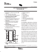
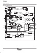
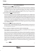
TYPICAL BUCK APPLICATION
APPLICATIONS
D Networking Equipment
D Servers
D Base Stations
D Cellular Telephones
D Satellite Telephones
D GPS Devices
D Digital Still and Handheld Cameras
D Personal Digital Assistants (PDAs)
DESCRIPTION
The TPS43000 is a high-frequency, voltage-mode,
synchronous PWM controller that can be used in buck,
boost, SEPIC, or flyback topologies. This highly flexible,
full-featured controller is designed to drive a pair of
external MOSFETs (one N-channel and one
P-channel), enabling it for use with a wide range of
output voltages and power levels. With an automatic
PFM mode, a shutdown current of less than 1 µA, a
sleep-mode current of less than 100 µA and a full
operating current of less than 2 mA at 1 MHz, it is ideal
for building highly efficient, dc-to-dc converters.
The TPS43000 operates over a wide input voltage
range of 1.8 V to 9.0 V. Typical power sources are
distributed power systems, two to four nickel or alkaline
batteries, or one to two lithium-ion cells. It can be used
to generate regulated output voltages from as low as
0.8 V to 8 V or higher. It operates either in a
fixed-frequency mode, where the user programs the
frequency (up to 2 MHz), or in an automatic PFM mode.
In the automatic mode, the controller goes to sleep
when the inductor current goes discontinuous, and
wakes up when the output voltage has fallen by 2%. In
this hysteretic mode of operation, very high efficiency
can be maintained over a very wide range of load
current. The device can also be synchronized to an
external clock source using the dual function SYNC/SD
input pin.
UDG−01036
5
1
3
4
2
6
12
7
SYNC/SD
CCS
RT
CCM
BUCK
PFM*
COMP FB
TPS43000
8
10
11
16
15
13
14
9
VIN
VOUT
NDRV
GND
PDRV
VP
SWP
SWN
RTN
VIN
VOUT
Copyright 2001, Texas Instruments Incorporated
! " #$%! " &$'(#! )!%*
)$#!" # ! "&%##!" &% !+% !%" %," "!$%!"
"!)) -!.* )$#! &#%""/ )%" ! %#%""(. #($)%
!%"!/ (( &%!%"*
Please be aware that an important notice concerning availability, standard warranty, and use in critical applications of Texas Instruments
semiconductor products and disclaimers thereto appears at the end of this data sheet.