
Datasheet


www.ti.com
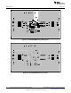
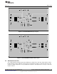
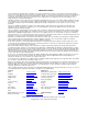
Board Layout
Figure 21. TPS43061EVM-198 Layer 3 Layout
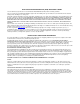
Figure 22. TPS43061EVM-198 Bottom-Side Layout
4.2 Estimated Circuit Area
The estimated printed-circuit-board area by outlining the components used in this design and the routing
between them is 0.91 in
2
(590 mm
2
). This area does not include test points or connectors. Also note, this
design uses 0603 components for easy modifications and places all components on one layer so this area
may be reduced.
15
SLVU799A–November 2012–Revised March 2013 Using the TPS43061 Boost Evaluation Module (EVM)
Submit Documentation Feedback
Copyright © 2012–2013, Texas Instruments Incorporated