
Datasheet


SLUS571 − SEPTEMBER 2003
9
www.ti.com
FUNCTIONAL DESCRIPTION
STANDBY
The SBRC controller can be switched into standby mode separately by grounding STBY pin.
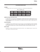
Table 1. Standby Logic
STBY1 STBY2 SBRC (CH1) SBRC (CH2) 5-V REGULATOR
L L DISABLED DISABLED DISABLED
L H DISABLED ENABLED ENABLED
H L ENABLED DISABLED ENABLED
H H ENABLED ENABLED ENABLED
UNDERVOLTAGE LOCK OUT (UVLO)
For undervoltage lock out (UVLO), the TPS5124 monitors VREF5 voltage. When the VREF5 voltage decreases
below about 4.1 V, the output stages of both SBRC are turned off. This state is not latched and the operation
recovers immediately after the input voltage becomes higher than about 4.2 V again. The typical hysteresis
voltage is 40 mV.
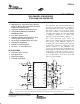
PHASE INVERTER
The SBRC (CH2) of the TPS5124 operates in the same phase as the internal triangular oscillator output while
the SBRC (CH1) operates 180_ out of phase. When the SBRC (CH1) and the SBRC (CH2) share the same input
power supply, the TPS5124 reduces input current ripple and enables the input capacitor value smaller.
OSCILLATOR
TPS5124 has a triangle oscillator generator internal to the device. The oscillation frequency is set by the size
of the capacitor connected to the CT pin.