
Datasheet


User's Guide
SLVU373A–March 2010–Revised May 2012
TPS53114EVM-541
The TPS53114EVM-541 evaluation module can demonstrate a wide-input-voltage (5 V–22 V) to 1.20-V, 4-
A application in a stand-alone module. This module allows a customer to evaluate the performance of the
TPS53114 controller in a typical synchronous, buck (step-down) application. Specifications, test procedure
and setup, design files, and typical performance are included for reference.
Contents
1 Introduction .................................................................................................................. 2
1.1 Description .......................................................................................................... 2
1.2 Applications ......................................................................................................... 2
1.3 Features ............................................................................................................. 2
2 TPS53114EVM-541 Electrical Performance Specifications ........................................................... 2
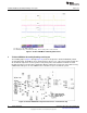
3 TPS53114EVM-541 Schematic ........................................................................................... 3
4 Connector and Test Point Descriptions .................................................................................. 4
4.1 Enable Switch and Enable Sense – SW1 and JP2 ............................................................ 4
4.2 Frequency Selection Switch and Frequency Sense – SW2 and JP1 ....................................... 4
4.3 Test Point Descriptions ............................................................................................ 4
5 Test Setup (Optional) ....................................................................................................... 5
5.1 Equipment ........................................................................................................... 5
5.2 Equipment Setup ................................................................................................... 6
5.3 Start-Up/Shutdown Procedure ................................................................................... 7
5.4 Output Ripple Voltage Measurement Procedure .............................................................. 8
5.5 Equipment Shutdown .............................................................................................. 8
6 TPS53114EVM-541 Test Data ............................................................................................ 8
6.1 Efficiency ............................................................................................................ 8
6.2 Line and Load Regulation ......................................................................................... 9
6.3 Output Voltage Ripple ............................................................................................. 9
6.4 Switch Node ....................................................................................................... 10
7 TPS53114EVM-541 Assembly Drawings and Layout ................................................................ 10
8 TPS53114EVM-541 Bill of Materials .................................................................................... 12
List of Figures
1 TPS53114EVM-541 Schematic ........................................................................................... 3
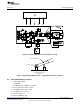
2 TPS53114EVM-541 Recommended Test Setup ....................................................................... 7
3 Output Ripple Measurement – Tip and Barrel Using TP3 and TP4 .................................................. 7
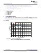
4 TPS53114EVM-541 Efficiency Versus Load Current .................................................................. 8
5 TPS53114EVM-541 Output Voltage Versus Load Current............................................................ 9
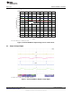
6 TPS53114EVM-541 Output Voltage Ripple ............................................................................. 9
7 TPS53114EVM-541 Switching Waveforms ............................................................................ 10
8 TPS53114EVM-541 Component Placement – Viewed From Top .................................................. 10
9 TPS53114EVM-541 Top Copper –Viewed From Top ................................................................ 11
10 TPS53114EVM-541 Bottom Copper – Viewed From Bottom........................................................ 11
11 TPS53114EVM-541 Internal 1 - X-Ray View From Top.............................................................. 12
12 TPS53114EVM-541 Internal 2 – X-Ray View From Top ............................................................. 12
List of Tables
1
SLVU373A–March 2010–Revised May 2012 TPS53114EVM-541
Submit Documentation Feedback
Copyright © 2010–2012, Texas Instruments Incorporated