
Power Supply User Manual

User's Guide
SLVU392–July 2010
TPS53125EVM-599
The TPS53125EVM-599 Evaluation Module presents an easy-to-use reference design for a common dual
output power supply using the TPS53125 controller in cost-sensitive applications. Also included are the
schematic, board layout, and bill of materials.
Contents
1 Description ................................................................................................................... 2
1.1 Applications ......................................................................................................... 2
1.2 Features ............................................................................................................. 2
2 TPS53125EVM-599 Electrical Performance Specifications ........................................................... 2
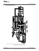
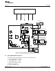
3 TPS53125EVM-599 Schematic ........................................................................................... 3
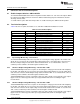
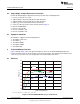
4 Connector and Test Point Descriptions .................................................................................. 4
4.1 Enable Jumpers/Switches –SW1 and SW2 .................................................................... 4
4.2 Test Point Descriptions ............................................................................................ 4
5 Test Setup ................................................................................................................... 5
5.1 Equipment ........................................................................................................... 5
5.2 Equipment Setup ................................................................................................... 6
5.3 Start-Up/Shutdown Procedures .................................................................................. 7
5.4 Output Ripple Voltage Measurement Procedure .............................................................. 8
5.5 Equipment Shutdown .............................................................................................. 8
6 TPS53125EVM-599 Test Data ............................................................................................ 8
6.1 Efficiency ............................................................................................................ 8
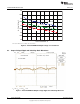
6.2 Line and Load Regulation ......................................................................................... 9
6.3 Output Voltage Ripple and Switching Node Waveforms .................................................... 10
6.4 Switch Node ....................................................................................................... 11
7 TPS53125EVM-599 Assembly Drawings and Layout ................................................................ 12
8 TPS53125EVM-599 Bill of Materials .................................................................................... 15
List of Figures
1 TPS53125EVM-599 Schematic ........................................................................................... 3
2 TPS53125EVM-599 Recommended Test Setup ....................................................................... 7
3 TPS53125EVM-599 Efficiency vs Load Current ........................................................................ 8
4 TPS53125EVM-599 Efficiency vs Load Current ........................................................................ 9
5 TPS53125EVM-599 Output Voltage vs Load Current ................................................................. 9
6 TPS53125EVM-599 Output Voltage vs Load Current ................................................................ 10
7 TPS53125EVM-599 Output Voltage Ripple and Switching Waveform............................................. 10
8 TPS53125EVM-599 Output Voltage Ripple............................................................................ 11
9 TPS53125EVM-599 Switching Waveforms ............................................................................ 11
10 TPS53125EVM-599 Switching Waveforms ............................................................................ 12
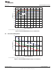
11 TPS53125EVM-599 Component Placement, Viewed From Top.................................................... 12
12 TPS53125EVM-599 Top Copper, Viewed From Top ................................................................. 13
13 TPS53125EVM-599 Bottom Copper, Viewed From Bottom ......................................................... 13
14 TPS53125EVM-599 Internal 1, X-Ray View From Top............................................................... 14
15 TPS53125EVM-599 Internal 2, X-Ray View From Top............................................................... 14
D-CAP2 is a trademark of Texas Instruments.
1
SLVU392–July 2010 TPS53125EVM-599
Copyright © 2010, Texas Instruments Incorporated