
Power Supply User Manual
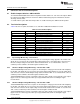
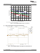

0 1 2 3 4 5
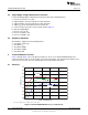
I -LoadCurrent- A
LOAD
50
55
60
65
70
75
80
85
90
95
h -Efficiency-%
V =8V
I
V =12V
I
V =22V
I
TPS53125EVM-599 Test Data
www.ti.com
7. Decrease LOAD2 to 0 A.
5.4 Output Ripple Voltage Measurement Procedure
Perform the Output Ripple Voltage Measurement procedure in the following manner.
1. Increase V
IN
from 0 V to 12 Vdc.
2. Adjust LOAD1 to desired load between 0 Adc and 4 Adc.
3. Adjust LOAD2 to desired load between 0 Adc and 4 Adc.
4. Adjust V
IN
to desired load between 8 Vdc and 22 Vdc.
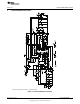
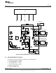
5. Connect oscilloscope probe to CN1 or CN2 shown in Figure 2.
6. Measure Output Ripple.
7. Decrease V
IN
to 0 Vdc.
8. Decrease LOAD1 to 0 A.
9. Decrease LOAD2 to 0 A.
5.5 Equipment Shutdown
Shut down the equipment in the following manner.
1. Shut down oscilloscope.
2. Shut down V
IN
.
3. Shut down LOAD1.
4. Shut down LOAD2.
5. Shut down FAN.
6 TPS53125EVM-599 Test Data
Figure 3 through Figure 10 present typical performance curves for the TPS53125EVM-599. Because
actual performance data can be affected by measurement techniques and environmental variables, these
curves are presented for reference and may differ from actual field measurements.
6.1 Efficiency
V
IN
= 8 V – 22 V, V
OUT1
= 1.05 V, I
OUT1
= 0 A – 4 A
Figure 3. TPS53125EVM-599 Efficiency vs Load Current
8
TPS53125EVM-599 SLVU392–July 2010
Copyright © 2010, Texas Instruments Incorporated