
Datasheet


User's Guide
SLVU728–May 2012
High Efficiency 14A Synchronous Buck Converter with
Eco-Mode™
The TPS53319EVM-136 is designed to use a regulated 12V bus to produce a regulated 1.5V output at up
to 14A of load current. The TPS53319EVM-136 is designed to demonstrate the TPS53319 in a typical low
voltage application while providing a number of test points to evaluate the performance of the TPS53319.
Contents
1 Introduction .................................................................................................................. 3
1.1 Typical Applications ................................................................................................ 3
1.2 Features ............................................................................................................. 3
2 Electrical Performance Specifications .................................................................................... 3
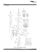
3 Schematic .................................................................................................................... 4
4 Test Setup ................................................................................................................... 5
4.1 Test Equipment ..................................................................................................... 5
4.2 Recommended Test Setup ....................................................................................... 6
5 Configurations ............................................................................................................... 6
5.1 Switching Frequency Selection .................................................................................. 6
5.2 Soft Start Selection ................................................................................................ 7
5.3 Mode Selection ..................................................................................................... 7
5.4 Enable Selection ................................................................................................... 7
6 Test Procedure .............................................................................................................. 8
6.1 Line/Load Regulation and Efficiency Measurement Procedure .............................................. 8
6.2 Control Loop Gain and Phase Measurement Procedure ..................................................... 8
6.3 List of Test Points .................................................................................................. 8
6.4 Equipment Shutdown .............................................................................................. 9
7 Performance Data and Typical Characteristic Curves ................................................................. 9
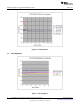
7.1 Efficiency ............................................................................................................ 9
7.2 Load Regulation .................................................................................................. 10
7.3 Line Regulation ................................................................................................... 10
7.4 Enable Turn on/ Turn off ........................................................................................ 11
7.5 Output Ripple ..................................................................................................... 11
7.6 Switching Node ................................................................................................... 12
7.7 Output Transient with Auto-skip mode ......................................................................... 12
7.8 Output Transient with FCCM mode ............................................................................ 13
7.9 Output 0.75V Pre-bias Turn on ................................................................................. 13
7.10 Output Over Current and Short Circuit Protection ........................................................... 13
7.11 Bode plot ........................................................................................................... 14
7.12 Thermal Image .................................................................................................... 15
8 EVM Assembly Drawing and PCB Layout ............................................................................. 16
9 Bill of Materials ............................................................................................................. 24
List of Figures
1 TPS53319EVM-136 Schematic ........................................................................................... 4
2 Tip and Barrel Measurement for Vout Ripple ........................................................................... 5
3 TPS53319EVM-136 Recommended Test Set Up ...................................................................... 6
4 Efficiency..................................................................................................................... 9
1
SLVU728–May 2012 High Efficiency 14A Synchronous Buck Converter with Eco-Mode™
Submit Documentation Feedback
Copyright © 2012, Texas Instruments Incorporated