
Datasheet


www.ti.com
5 Load Regulation ........................................................................................................... 10
6 Line Regulation ............................................................................................................ 10
7 Enable Turn on ............................................................................................................ 11
8 Enable Turn off ............................................................................................................ 11
9 Output Ripple .............................................................................................................. 11
10 Switching Node ............................................................................................................ 12
11 Output Transient from DCM to CCM.................................................................................... 12
12 Output Transient from CCM to DCM.................................................................................... 12
13 Output Transient with FCCM mode .................................................................................... 13
14 Output 0.75V Pre-bias Turn on .......................................................................................... 13
15 Output Over Current Protection ......................................................................................... 13
16 Output Over Voltage Protection ........................................................................................ 13
17 Bode plot at 12Vin, 1.5V/14A ............................................................................................ 14
18 Top Board at 12Vin, 1.5V/14A, 25deg.C amb. without airflow ...................................................... 15
19 TPS53319EVM-136 Top Layer Assembly Drawing................................................................... 16
20 TPS53319EVM-136 Bottom Assembly Drawing ...................................................................... 17
21 TPS53319EVM-136 Top Copper ....................................................................................... 18
22 TPS53319EVM-136 Layer 2 Copper ................................................................................... 19
23 TPS53319EVM-136 Layer 3 Copper ................................................................................... 20
24 TPS53319EVM-136 Layer 4 Copper ................................................................................... 21
25 TPS53319EVM-136 Layer 5 Copper ................................................................................... 22
26 TPS53319EVM-136 Bottom Layer Copper ............................................................................ 23
List of Tables
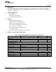
1 TPS53319EVM-136 Electrical Performance Specifications ........................................................... 3
2 Switching Frequency Selection ........................................................................................... 7
3 Soft Start Time Selection .................................................................................................. 7
4 MODE Selection ............................................................................................................ 7
5 Enable Selection ............................................................................................................ 7
6 The Functions of Each Test Points ....................................................................................... 8
7 Complonents List .......................................................................................................... 24
2
High Efficiency 14A Synchronous Buck Converter with Eco-Mode™ SLVU728–May 2012
Submit Documentation Feedback
Copyright © 2012, Texas Instruments Incorporated