
Datasheet


Test Procedure
www.ti.com
6 Test Procedure
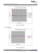
6.1 Line/Load Regulation and Efficiency Measurement Procedure
1. Set up EVM as described in Section 4 and Figure 3.
2. Ensure Load is set to constant resistance mode and to sink 0Adc
3. Ensure all jumpers configuration settings per section 5.
4. Ensure the jumper provided in the EVM shorts on J6 before Vin is applied.
5. Increase Vin from 0V to 12V. Using V1 to measure input voltage.
6. Remove the jumper on J6 to enable the controller.
7. Use V2 to measure Vout voltage.
8. Vary Load from 0-14Adc, Vout should be remain in load regulation.
9. Vary Vin from 8V to 20V, Vout should remain in line regulation.
10. Put the jumper on J6 to disable the controller.
11. Decrease Load to 0A
12. Decrease Vin to 0V.
6.2 Control Loop Gain and Phase Measurement Procedure
TPS53319EVM-136 contains a 10Ω series resistor in the feedback loop for loop response analysis.
1. Set up EVM as described in Section 4 and Figure 3.
2. Connect isolation transformer to test points marked TP6 and TP7.
3. Connect input signal amplitude measurement probe (channel A) to TP6. Connect output signal
amplitude measurement probe (channel B) to TP7.
4. Connect ground lead of channel A and channel B to TP9.
5. Inject around 20mV or less signal through the isolation transformer.
6. Sweep the frequency from 100Hz to 1MHz with 10Hz or lower post filter. The control loop gain and
phase margin can be measured.
7. Disconnect isolation transformer from bode plot test points before making other measurements (Signal
injection into feedback may interfere with accuracy of other measurements).
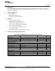
6.3 List of Test Points
Table 6. The Functions of Each Test Points
Test Points Name Description
TP1 VIN Controller input
TP2 Vout Output Voltage
TP3 VREG 5V LDO output
TP4 PGOOD Power Good
TP5 EN Enable
TP6 CHA Input A for loop injection
TP7 CHB Input B for loop injection
TP8 LL Switching node
TP9 GND Ground
TP10 GND Ground
TP11 GND Ground
TP12 GND Ground
8
High Efficiency 14A Synchronous Buck Converter with Eco-Mode™ SLVU728–May 2012
Submit Documentation Feedback
Copyright © 2012, Texas Instruments Incorporated