
Datasheet

Board Layout
www.ti.com
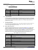
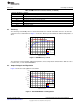
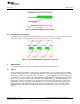
The input decoupling capacitor C4 and bootstrap capacitor C5 are both located as close to the IC as
possible. Additionally, the voltage set-point resistor divider components are kept close to the IC. The
location of the connection to the voltage divider network at R5 defines the point of regulation, which is the
copper VOUT trace at the output connector J3. For the TPS54020, an additional input bulk capacitor is
included to effectively reduce the source impedance from the input supply to the switcher. Critical analog
circuits such as the voltage setpoint divider, frequency set resistor, slow-start capacitor, and compensation
components are terminated to analog ground (AGND) using a ground trace that is separate from the
power ground plane.
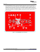
Figure 12. TPS54020EVM-082 Top Side Copper
10
TPS54020EVM-082 Evaluation Module (PWR082) SLVU777–September 2012
Submit Documentation Feedback
Copyright © 2012, Texas Instruments Incorporated