
Datasheet
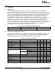

1.8
1.805
1.81
1.815
1.82
1.825
1.83
1.835
1.84
0 1 2 3 4 5 6 7 8 9 10
Output Current (A)
V
OUT
(V)
V
IN
= 5 V
V
IN
= 12 V
V
IN
= 17 V
Temp = 25°C
G007
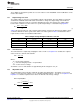
50
55
60
65
70
75
80
85
90
95
100
0 1 2 3 4 5 6 7 8 9 10
Output Current (A)
Efficiency (%)
V
IN
= 5 V
V
IN
= 12 V
V
IN
= 17 V
Temp = 25°C
G006
www.ti.com
Test Setup and Results
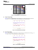
Table 4. EVM Connectors and Test Points (continued)
Reference Designator Function
TP8 Test point for PGND, near output.
TP9 Test point between voltage divider network and output. Used for loop response measurements.
TP10 Test point for ENABLE.
TP11 Test point for the timing resistor RT and Clock.
TP12 Test point for slow start.
TP13 Test point for AGND.
TP14 Test point for AGND.
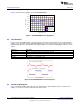
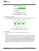
2.2 Efficiency
The efficiency of this EVM peaks at a load current between 3 A and 6 A and then decreases as the load
current increases toward full load. Figure 1 shows the efficiency for the EVM at an ambient temperature of
25°C.
Figure 1. EVM Efficiency at 25°C
The efficiency is lower at higher ambient temperatures, due to temperature variation in the drain-to-source
resistance R
DS_ON
of the internal MOSFETs.
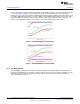
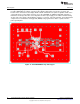
2.3 Output Voltage Load Regulation
Figure 2 shows the load regulation for the EVM.
Figure 2. TPS54020EVM-082 Load Regulation
5
SLVU777–September 2012 TPS54020EVM-082 Evaluation Module (PWR082)
Submit Documentation Feedback
Copyright © 2012, Texas Instruments Incorporated