
Datasheet

Time = 5 ms/div
V = 5 V/div
IN
I = 2 A/div
OUT
V = 500 mV/div
OUT
EN = 2 V/div
I = 2 A
OUT
/div
V = 5 V
IN
/div
Time = 5 ms/div
V = 500
OUT
mV/div
Test Setup and Results
www.ti.com
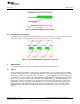
2.9 Start Up
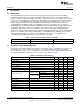
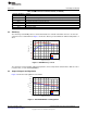
Figure 8 and Figure 9 show the start-up waveforms for the EVM. In Figure 8, the output voltage ramps up
as soon as the input voltage reaches the UVLO threshold as set by the R6 and R11 resistor divider
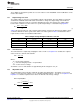
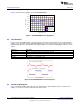
network. In Figure 9, the input voltage is initially applied and the output is inhibited by using a jumper at J5
to tie EN to GND. When the jumper is removed, EN is released. When the EN voltage reaches the enable
threshold voltage, the start-up sequence begins and the output voltage ramps up to the externally set
value of 1.8 V. The input voltage for these plots is 12 V and the load is 10-A resistive load.
Figure 8. TPS54020EVM-082 Start Up with V
IN
Figure 9. TPS54020EVM-082 Start Up with EN
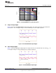
2.10 Pre-Bias Start Up
The TPS54020 is designed to start up into a pre-biased output. The output voltage is not discharged to
ground at the beginning of the slow-start sequence, but only starts to increase towards regulation once the
slow start voltage reaches the pre-bias bus voltage. Figure 10 shows the start-up waveform with the
output voltage pre-biased to 1 V.
8
TPS54020EVM-082 Evaluation Module (PWR082) SLVU777–September 2012
Submit Documentation Feedback
Copyright © 2012, Texas Instruments Incorporated