
Datasheet


www.ti.com
Configuration
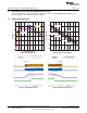
5.1.7 IMVP-7 VR_ON Enable Selection (S4)
The IMVP-7 CPU/GPU can be enabled and disabled by S4
Default setting: Push S4 to “OFF” position to disable both CPU and GPU
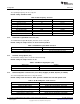
Table 8. VR_ON Enable Selection
Switch set to VR_ON Selection
Push S4 to “ON” position Enable IMVP-7 CPU/GPU Vcore
Push S4 to “OFF” position Disable IMVP-7 CPU/GPU Vcore
5.2 1.2VDDQ, 0.6V VTT and 0.6V VTTREF Configuration
5.2.1 VDDQ S3, S5 Enable Selection
The controller can be enabled and disabled by J18 and J17.
Default setting: Jumper shorts on Pin2 and Pin3 of J18,
Def ault setti ng : Jumper shorts on Pin2 and Pin3 of J17
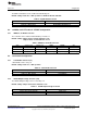
Table 9. VDDQ S3, S5 Enable Selection
State J17 (S3) set to J18(S5) set to VDDQ VTTREF VTT
S0 ON position ON position ON ON ON
S3 OFF position ON position ON ON OFF(High-Z)
S4/S5 OFF position OFF position OFF(Discharge) OFF(Discharge) OFF(Discharge)
5.3 1.05V VCCIO Configuration
5.3.1 1.05V Enable Selection (S1)
1.05V Enable can be set by S1
Default setting: Push S1 to ”OFF” position
Table 10. 1.05V Enable Selection
Jumper set to Selection
Push S1 to “ON” position 1.05V Enabled
Push S1 to “OFF” position 1.05V Disabled
5.3.2 VCCIO Output Voltage Selection (J14)
The VCCIO Output Voltage can be selected by J14
Default setting: Jumper shorts Pin1 and Pin2 of J14
Table 11. VCCIO Output Voltage Selection
Jumper set to Selection
Jumper shorts on Pin1 and Pin2 VCCIO: 1.05V
Jumper shorts on Pin2 and Pin3 VCCIO: 1.00V
13
SLUU896–March 2012 Using the TPS59650EVM-753 Intel™ IMVP-7 3-Phase CPU/2-Phase GPU
SVID Power System
Submit Documentation Feedback
Copyright © 2012, Texas Instruments Incorporated