
Datasheet


TPS60120, TPS60121, TPS60122, TPS60123, TPS60124, TPS60125
REGULATED 200-mA HIGH EFFICIENCY CHARGE PUMP
DC/DC CONVERTERS
SLVS257B – NOVEMBER 1999 – REVISED AUGUST 2000
1
POST OFFICE BOX 655303 • DALLAS, TEXAS 75265
features
High Average Efficiency Over Input Voltage
Range Because of Special Switching
Topology
Minimum 200-mA Output Current From an
Input Voltage Range of 1.8-V to 3.6-V
Regulated 3.3-V or 3-V ±4% Output Voltage
No Inductors Required, Low EMI
Only Four External Components Required
55-µA Quiescent Supply Current
0.05-µA Shutdown Current
Load Disconnected in Shutdown
Integrated Low Battery and Power Good
Detectors
Evaluation Module Available
(TPS60120EVM-142)
applications
Applications Powered by Two Battery Cells
Portable Instruments
Battery-Powered Microprocessor Systems
Miniature Equipment
Backup-Battery Boost Converters
PDAs, Organizers, Laptops
MP-3 Portable Audio Players
Handheld Instrumentation
Medical Instruments (e.g., Glucose Meters)
Cordless Phones
·
description
The TPS6012x step-up, regulated charge pumps
generate a 3.3-V or 3-V ±4% output voltage from
a 1.8-V to 3.6-V input voltage (two alkaline, NiCd,
or NiMH batteries). They can deliver an output
current of at least 200 mA (100 mA for the
TPS60122 and TPS60123), all from a 2-V input.
Four external capacitors are needed to build a
complete high efficiency dc/dc charge pump
converter. To achieve the high efficiency over a
wide input voltage range, the charge pump
automatically selects between a 1.5x or doubler
conversion mode. From a 2-V input, all ICs can
start with full load current.
The devices feature the power-saving pulse-skip
mode to extend battery life at light loads.
TPS60120, TPS60122, and TPS60124 include a
low battery comparator. TPS60121, TPS60123,
and TPS60125 feature a power-good output. The
logic shutdown function reduces the supply
current to a maximum of 1 µA and disconnects the
load from the input. Special current-control
circuitry prevents excessive current from being
drawn from the battery during start-up. This dc/dc
converter requires no inductors, therefore EMI is
of low concern. It is available in the small,
thermally enhanced 20-pin PowerPAD package
(PWP).
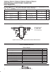
I
O
= 66 mA
0
10
20
30
40
50
60
70
80
90
100
1.8 2 2.2 2.4 2.6 2.8 3 3.2 3.4 3.6
V
I
– Input Voltage – V
Efficiency – %
I
O
= 164 mA
I
O
= 216 mA
I
O
= 116 mA
V
O
= 3.3 V
T
C
= 25°C
IN
IN
LBI
C1+
C1–
ENABLE
PGND GND
OUT
OUT
FB
LBO
C2+
C2–
C
O
22 µF
C
i
10 µF
Output
3.3 V
C2
2.2 µF
C1
2.2 µF
R1
R2
Input
1.8 V to 3.6 V
OFF/ON
efficiency (TPS60120, TPS60121)
typical operating circuit
R3
TPS60120
Copyright 2000, Texas Instruments Incorporated
Please be aware that an important notice concerning availability, standard warranty, and use in critical applications of
Texas Instruments semiconductor products and disclaimers thereto appears at the end of this data sheet.
PRODUCTION DATA information is current as of publication date.
Products conform to specifications per the terms of Texas Instruments
standard warranty. Production processing does not necessarily include
testing of all parameters.
PowerPAD is a trademark of Texas Instruments Incorporated.