
Datasheet

TPS60200, TPS60201, TPS60202, TPS60203
REGULATED 3.3 V, 100-mA LOW-RIPPLE CHARGE PUMP
LOW POWER DC/DC CONVERTERS
SLVS274 – MARCH 2000
1
POST OFFICE BOX 655303 • DALLAS, TEXAS 75265
features
Regulated 3.3-V Output Voltage With up to
100-mA Output Current From a 1.8-V to
3.6-V Input Voltage
Less Than 5-mV
(PP)
Output Voltage Ripple
Achieved With Push-Pull Topology
Integrated Low-Battery and Power-Good
Detector
Switching Frequency Can Be Synchronized
to External Clock Signal
Extends Battery Usage With up to 90%
Efficiency and 35-µA Quiescent Supply
Current
Reliable System Shutdown Because Output
Capacitor Is Discharged When Device Is
Disabled
Easy-To-Design, Low-Cost, Low-EMI Power
Supply Since No Inductors Are Used
0.05-µA Shutdown Current, Battery Is
Isolated From Load in Shutdown Mode
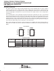
Compact Converter Solution in UltraSmall
10-pin MSOP With Only Four External
Capacitors Required
Evaluation Module Available
(TPS60200EVM-145)
applications
Replaces DC/DC Converters With Inductors
in Battery Powered Applications Like:
– Two Battery Cells to 3.3-V Conversion
– MP3 Portable Audio Players
– Battery-Powered Microprocessor
Systems
– Backup-Battery Boost Converters
– PDA’s, Organizers, and Cordless Phones
– Handheld Instrumentation
– Glucose Meters and Other Medical
Instruments
·
description
The TPS6020x step-up, regulated charge pumps generate a 3.3-V ±4% output voltage from a 1.8-V to 3.6-V
input voltage. The devices are typically powered by two Alkaline, NiCd or NiMH battery cells and operate down
to a minimum supply voltage of 1.6 V. Continuous output current is a minimum of 100 mA for the TPS60200 and
TPS60201 and 50 mA for the TPS60202 and TPS60203, all from a 2-V input. Only four external capacitors are
needed to build a complete low-ripple dc/dc converter. The push-pull operating mode of two single-ended
charge pumps assures the low output voltage ripple as current is continuously transferred to the output.
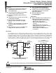
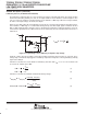
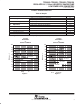
Figure 1. Typical Application Circuit
With Low-Battery Warning
TPS60200
PEAK OUTPUT CURRENT
vs
INPUT VOLTAGE
150
100
50
0
1.6 2.0 2.4 2.8
200
250
350
3.2 3.6
300
V
I
– Input Voltage – V
– Peak Output Current – mA
OUTPUT
3.3 V, 100 mA
INPUT
1.6 V to 3.6 V
OFF/ON
C1
C2
R1
R2
1
2
3
4
5
6
7
8
9
10
R3
Low Battery
Warning
IN
EN
C1–
C1+
LBI
TPS60200
OUT
C2–
C2+
LBO
GND
O
I
C
i
C
o
1 µF
1 µF
2.2 µF
2.2 µF
Copyright 2000, Texas Instruments Incorporated
Please be aware that an important notice concerning availability, standard warranty, and use in critical applications of
Texas Instruments semiconductor products and disclaimers thereto appears at the end of this data sheet.
PRODUCTION DATA information is current as of publication date.
Products conform to specifications per the terms of Texas Instruments
standard warranty. Production processing does not necessarily include
testing of all parameters.