User’s Guide July 2004 PMP Portable Power Products SBVU008
IMPORTANT NOTICE Texas Instruments Incorporated and its subsidiaries (TI) reserve the right to make corrections, modifications, enhancements, improvements, and other changes to its products and services at any time and to discontinue any product or service without notice. Customers should obtain the latest relevant information before placing orders and should verify that such information is current and complete.
EVM IMPORTANT NOTICE Texas Instruments (TI) provides the enclosed product(s) under the following conditions: This evaluation kit being sold by TI is intended for use for ENGINEERING DEVELOPMENT OR EVALUATION PURPOSES ONLY and is not considered by TI to be fit for commercial use.
EVM WARNINGS AND RESTRICTIONS It is important to operate this EVM within the input voltage range of 0 V and 7 V. Exceeding the specified input range may cause unexpected operation and/or irreversible damage to the EVM. If there are questions concerning the input range, please contact a TI field representative prior to connecting the input power. Applying loads outside of the specified output range may result in unintended operation and/or possible permanent damage to the EVM.
Preface Read This First About This Manual This user’s guide provides the information needed to set up and operate the TPS60230EVM-047 evaluation module. For a more detailed description of the TPS60230, please refer to the product data sheet available from the Texas Instruments web site at http://www.ti.com. Additional support documents are listed in the sections of this guide entitled Related Documentation from Texas Instruments.
Contents If You Need Assistance If you have questions regarding either the use of this evaluation module or the information contained in the accompanying documentation, please contact your local TI sales representative, the Texas Instruments Product Information Center at (972) 644−5580, or visit the TI Semiconductor Online Technical Support pages at http://www.ti.com. FCC Warning This equipment is intended for use in a laboratory test environment only.
TPS60230EVMĆ047 This user’s guide describes the characteristics, operation, and use of the TPS60230EVM-047 LED charge-pump current-source evaluation module (EVM). This EVM features a high-efficiency charge-pump-based white LED driver designed to operate off a single cell Li-Ion battery and drive up to five white LEDs with up to 20mA each.
Introduction 1 Introduction The Texas Instruments TPS60230EVM-047 evaluation module (EVM) helps designers evaluate the operation and performance of the TPS60230. This device is an efficient charge-pump-based current sink that can drive up to five white LEDs with 25mA each. Efficiency is improved by switching between a 1.0x and 1.5x mode, based on the input voltage. This EVM is specifically designed and optimized to operate with a single-cell Li-Ion battery input.
Input/Output Connector Descriptions 2.2 Setup Connect an input supply or battery between J1 and J2. The voltage range on this supply should stay between 2.7V and 6.0V. Set the appropriate brightness by configuring JP1 and JP2. 2.3 Operation The EVM has been optimized to operate from a single-cell Li-Ion battery with an input voltage range of 2.7V to 6.0V. The value for R1 programs the maximum LED current. For this EVM, the maximum current is set to 20mA.
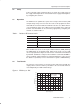
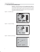
Printed Circuit Board (PCB) Layout 3 Printed Circuit Board (PCB) Layout PCB layout is critical for all switch-mode power supplies. Figure 2, Figure 3, and Figure 4 show the board layout for the TPS60230EVM-047 PWB. The nodes with high switching frequencies and currents are short and are isolated from the noise-sensitive feedback circuitry. Careful attention has been given to the routing of high-frequency current loops. Refer to the product datasheet (SLVS516) for specific layout guidelines. Figure 2.
Schematic 4 Schematic Figure 5. TPS60230EVM−047 Schematic 5 Bill of Materials Table 2. Bill of Materials Qty Ref Des Description Size Mfr Part Number 2 C1, C4 Capacitor, ceramic, 1.0µF, 6.3V, X5R, 10% 603 TDK C1608X5R0J105KT 2 C2, C3 Capacitor, ceramic, 0.47µF, 10V, X5R, 10% 603 TDK C1608X5R1A474KT 5 D1 − D5 Diode, LED, White, 30mA 1210 Lumex SML−LX2832UWC−TR 2 J1, J2 Header, 2-pin, 100mil spacing, (36-pin strip) 0.