
Datasheet

www.ti.com
FEATURES DESCRIPTION
APPLICATIONS
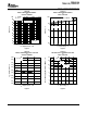
OFF
ON
OFF
ON
OFF
ON
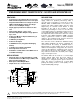
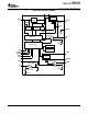
VBAT
LBI
SKIPEN
EN
LDOEN
SWN
VOUT
FB
PGOOD
LBO
LDOIN
LDOOUT
LDOSENSE
GND PGND
Control
Inputs
Control
Outputs
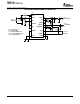
V
out1
V
out2
TPS61120
Battery
SWP
10 H
10 F
100 F
2.2 F
TPS61120
TPS61122, TPS61121
SLVS427C – JUNE 2002 – REVISED APRIL 2004
SYNCHRONOUS BOOST CONVERTER WITH 1.1A SWITCH AND INTEGRATED LDO
• Synchronous, 95% Efficient, Boost Converter
The TPS6112x devices provide a complete power
With 500-mA Output Current From 1.8-V Input
supply solution for products powered by either a
one-cell Li-Ion or Li-Polymer or a two up to 4 cells
• Integrated 200-mA Reverse Voltage Protected
Alkaline, NiCd or NiMH batteries. The devices can
LDO for DC/DC Output Voltage Post Regu-
generate two stable output voltages that are either
lation or Second Output Voltage
adjusted by an external resistor divider or fixed
• 40-µA (Typical) Total Device Quiescent Cur-
internally on the chip. It also provides a simple
rent
solution for generating 3.3 V out of a one-cell Li-Ion
or Li-Polymer battery at a maximum output current of
• Input Voltage Range: 1.8-V to 5.5-V
at least 200 mA with supply voltages down to 1.8 V.
• Fixed and Adjustable Output Voltage Options
The implemented boost converter is based on a fixed
up to 5.5-V
frequency, pulse-width-modulation (PWM) controller
• Power Save Mode for Improved Efficiency at
using a synchronous rectifier to obtain maximum
Low Output Power
efficiency. The maximum peak current in the boost
switch is limited to a value of 1600 mA.
• Low Battery Comparator
• Power Good Output
The converter can be disabled to minimize battery
drain. During shutdown, the load is completely dis-
• Low EMI-Converter (Integrated Antiringing
connected from the battery. A low-EMI mode is
Switch)
implemented to reduce ringing and in effect lower
• Load Disconnect During Shutdown
radiated electromagnetic energy when the converter
• Overtemperature Protection
enters the discontinuous conduction mode. A power
good output at the boost stage simplifies control of
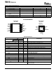
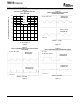
• Available in a Small 4mm x 4mm QFN-16 or in
any connected circuits like cascaded power supply
a TSSOP-16 Package
stages or microprocessors.
The built-in LDO can be used for a second output
voltage derived either from the boost output or
• All Single Cell Li or Dual Cell Battery or USB
directly from the battery. The LDO can be enabled
Powered Products as MP-3 Player, PDAs, and
separately i.e., using the power good of the boost
Other Portable Equipment
stage. The device is packaged in a 16-pin QFN
• Dual Input or Dual Output Mode
package measuring 4 mm x 4 mm (RSA) or in a
• Simple Li-Ion to 3.3-V Conversion
16-pin TSSOP (PW) package.
Please be aware that an important notice concerning availability, standard warranty, and use in critical applications of Texas
Instruments semiconductor products and disclaimers thereto appears at the end of this data sheet.
PRODUCTION DATA information is current as of publication date.
Copyright © 2002–2004, Texas Instruments Incorporated
Products conform to specifications per the terms of the Texas
Instruments standard warranty. Production processing does not
necessarily include testing of all parameters.