
Datasheet

1
FEATURES
APPLICATIONS
DESCRIPTION
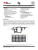
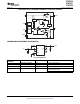
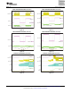
L
C
1
10µF
L
1
4.7
µ
H
VIN
VOUT
FB
C
2
10µ F
EN
GND
TPS61220
V
OUT
1.8Vto5.5V
R
1
R
2
0.7VtoV
OUT
V
IN
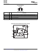
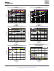
0.01
0.1
1
10
100
2.8
2.3
1.8
1.3
0.8
OUT
I
-OutputCurrent-mA
IN
V
-InputV
oltage-V
≥ 90%
≥ 80%
≥ 70%
OUT
(V
=3.3V)
EfficiencyvsOutputCurrentandInputVoltage
TPS61220
TPS61221
TPS61222
www.ti.com
............................................................................................................................................................................................... SLVS776 – JANUARY 2009
LOW INPUT VOLTAGE STEP-UP CONVERTER IN 6 PIN SC-70 PACKAGE
• Adjustable Output Voltage from 1.8 V to 5.5 V
• Up to 95% Efficiency at Typical Operating • Fixed Output Voltage Versions
Conditions
• Small 6-pin SC-70 Package
• 5.5 µ A Quiescent Current
• Startup Into Load at 0.7 V Input Voltage
• Battery Powered Applications
• Operating Input Voltage from 0.7 V to 5.5 V
– 1 to 3 Cell Alkaline, NiCd or NiMH
• Pass-Through Function during Shutdown
– 1 cell Li-Ion or Li-Primary
• Minimum Switching Current 200 mA
• Solar or Fuel Cell Powered Applications
• Protections:
• Consumer and Portable Medical Products
– Output Overvoltage
• Personal Care Products
– Overtemperature
• White or Status LEDs
– Input Undervoltage Lockout
• Smartphones
The TPS6122x family devices provide a power-supply solution for products powered by either a single-cell,
two-cell, or three-cell alkaline, NiCd or NiMH, or one-cell Li-Ion or Li-polymer battery. Possible output currents
depend on the input-to-output voltage ratio. The boost converter is based on a hysteretic controller topology
using synchronous rectification to obtain maximum efficiency at minimal quiescent currents. The output voltage of
the adjustable version can be programmed by an external resistor divider, or is set internally to a fixed output
voltage. The converter can be switched off by a featured enable pin. While being switched off, battery drain is
minimized. The device is offered in a 6-pin SC-70 package (DCK) measuring 2 mm x 2 mm to enable small
circuit layout size.
1
Please be aware that an important notice concerning availability, standard warranty, and use in critical applications of Texas
Instruments semiconductor products and disclaimers thereto appears at the end of this data sheet.
PRODUCTION DATA information is current as of publication date.
Copyright © 2009, Texas Instruments Incorporated
Products conform to specifications per the terms of the Texas
Instruments standard warranty. Production processing does not
necessarily include testing of all parameters.