
Datasheet
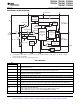
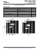

FUNCTIONAL BLOCK DIAGRAM
PFM/PWM
Control Logic
Current Limit
Logic
_
+
Compensation
Soft
Start
Slope Compensation
PFM/PWM
Mode Select
PFM/PWM
Comparator
Error Amplifier
_
+
Current
Sense
Driver
Shoot-Through
Logic
_
+
Undervoltage
Lockout
Bias Supply
10 Ω
_
+
V
ref
= 0.45 V
R2
R1
R1 + R2 ≈ 1 MΩ
Power Good
Sync
+
Oscillator
_
+
Load Comparator
Current Sense
+
Offset
Antiringing
FB
N-Channel
Power MOSFET
P-Channel
Power MOSFET
L
PGND
EN
FB
PG FC (See Note B) V
IN
GND SYNC ILIM
EN
(See
Note A)
TPS62000, TPS62001, TPS62003
TPS62004, TPS62005, TPS62006
TPS62007, TPS62008
www.ti.com
........................................................................................................................................... SLVS294E – SEPTEMBER 2000 – REVISED AUGUST 2008
A. The adjustable output voltage version does not use the internal feedback resistor divider. The FB pin is directly
connected to the error amplifier.
B. Do not connect the FC pin to an external power source
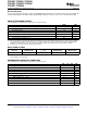
PIN FUNCTIONS
PIN
I/O DESCRIPTION
NAME NO.
Enable. A logic high enables the converter, logic low forces the device into shutdown mode reducing the supply
EN 8 I
current to less than 1 µ A.
Feedback pin for the fixed output voltage option. For the adjustable version an external resistive divider is
FB 5 I
connected to FB. The internal voltage divider is disabled for the adjustable version.
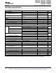
Supply bypass pin. A 0.1 µ F coupling capacitor should be connected as close as possible to this pin for good
FC 2
high frequency input voltage supply filtering.
GND 3 Ground
Switch current limit. Connect ILIM to GND to set the switch current limit to typically 600 mA, or connect this pin
ILIM 6 I
to V
IN
to set the current limit to typically 1200 mA.
L 9 I/O Connect the inductor to this pin. L is the switch pin connected to the drain of the internal power MOSFETS.
Power good comparator output. This is an open-drain output. A pullup resistor should be connected between
PG 4 O
PG and V
O
. The output goes active high when the output voltage is greater than 92% of the nominal value.
PGND 10 Power ground. Connect all power grounds to PGND.
Input for synchronization to external clock signal. Synchronizes the converter switching frequency to an
external clock signal with CMOS level:
SYNC 7 I
SYNC = HIGH: Low-noise mode enabled, fixed frequency PWM operation is forced
SYNC = LOW (GND): Power save mode enabled, PFM/PWM mode enabled.
V
IN
1 I Supply voltage input
Copyright © 2000 – 2008, Texas Instruments Incorporated Submit Documentation Feedback 3
Product Folder Link(s): TPS62000, TPS62001, TPS62003 TPS62004, TPS62005, TPS62006 TPS62007, TPS62008