
Datasheet

Low Noise Antiringing Switch
Soft Start
Enable
Undervoltage Lockout
Power Good Comparator
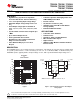
TPS62000, TPS62001, TPS62003
TPS62004, TPS62005, TPS62006
TPS62007, TPS62008
www.ti.com
........................................................................................................................................... SLVS294E – SEPTEMBER 2000 – REVISED AUGUST 2008
Connecting the SYNC pin to the GND pin enables the power save mode. The converter operates in the PWM
mode at moderate to heavy loads and in the PFM mode during light loads maintaining high efficiency over a wide
load current range.
Connecting the SYNC pin to the V
IN
pin forces the converter to operate permanently in the PWM mode even at
light or no load currents. The advantage is the converter operates with a fixed switching frequency that allows
simple filtering of the switching frequency for noise sensitive applications. In this mode, the efficiency is lower
compared to the power save mode during light loads (see Figure 1 ).
It is possible to switch from forced PWM mode to the power save mode during operation.
The flexible configuration of the SYNC pin during operation of the device allows efficient power management by
adjusting the operation of the TPS6200x to the specific system requirements.
An antiringing switch is implemented in order to reduce the EMI radiated from the converter during discontinuous
conduction mode (DCM). In DCM, the inductor current ramps to zero before the end of each switching period.
The internal load comparator turns off the low side switch at that instant thus preventing the current flowing
backward through the inductance which increases the efficiency. An antiringing switch across the inductor
prevents parasitic oscillation caused by the residual energy stored in the inductance (see Figure 12 ).
NOTE:
The antiringing switch is only activated in the fixed output voltage versions. It is not
enabled for the adjustable output voltage version TPS62000.
As the enable pin (EN) goes high, the soft-start function generates an internal voltage ramp. This causes the
start-up current to slowly rise preventing output voltage overshoot and high inrush currents. The soft-start
duration is typical 1 ms (see Figure 13 ). When the soft-start function is completed, the error amplifier is
connected directly to the internal voltage reference.
Logic low on EN forces the TPS6200x into shutdown. In shutdown, the power switch, drivers, voltage reference,
oscillator, and all other functions are turned off. The supply current is reduced to less than 1 µ A in the shutdown
mode.
An undervoltage lockout circuit provides the save operation of the device. It prevents the converter from turning
on when the voltage on V
IN
is less than typically 1.6 V.
The power good (PG) comparator has an open drain output capable of sinking typically 10 µ A. The PG is only
active when the device is enabled (EN = high). When the device is disabled (EN = low), the PG pin is high
impedance.
The PG output is only valid after a 100 µ s delay after the device is enabled and the supply voltage is greater
than 1.2 V. This is only important in cases where the pullup resistor of the PG pin is connected to an external
voltage source which might cause an initial spike (false high signal) within the first 100 µ s after the input voltage
exceeds 1.2 V. This initial spike can be filtered with a small R-C filter to avoid false power good signals during
start-up.
If the PG pin is connected to the output of the TPS62000 with a pullup resistor, no initial spike (false high signal)
occurs and no precautions have to be taken during start-up.
The PG pin becomes active high when the output voltage exceeds typically 94.5% of its nominal value. Leave
the PG pin unconnected when not used.
Copyright © 2000 – 2008, Texas Instruments Incorporated Submit Documentation Feedback 5
Product Folder Link(s): TPS62000, TPS62001, TPS62003 TPS62004, TPS62005, TPS62006 TPS62007, TPS62008