
Datasheet


www.ti.com
_
+
_
+
_
+
_
+
_
+
REF
REF
Load Comparator
Skip Comparator
Current Limit Comparator
P-Channel
Power MOSFET
Driver
Shoot-Through
Logic
Control
Logic
Soft Start
1 MHz
Oscillator
Comparator
S
R
N-Channel
Power MOSFET
Comparator High
Comparator Low
Comparator Low 2
V
(COMP)
Sawtooth
Generator
V
I
Undervoltage
Lockout
Bias Supply
_
+
Comparator High
Comparator Low
Comparator Low 2
Compensation
V
REF
= 0.5 V
R2
See Note
R1
V
I
EN
SW
FB GND
Gm
DETAILED DESCRIPTION
OPERATION
TPS62200 , , TPS62201
TPS62202 , TPS62203 , TPS62207
TPS62204 , TPS62205 , TPS62208
SLVS417E – MARCH 2002 – REVISED MAY 2006
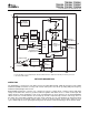
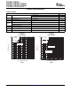
FUNCTIONAL BLOCK DIAGRAM
For the adjustable version (TPS62200) the internal feedback divider is disabled and the FB pin is directly connected
to the internal GM amplifier
The TPS6220x is a synchronous step-down converter operating with typically 1-MHz fixed frequency pulse width
modulation (PWM) at moderate to heavy load currents and in power save mode operating with pulse frequency
modulation (PFM) at light load currents.
During PWM operation the converter uses a unique fast response, voltage mode, controller scheme with input
voltage feed forward. This achieves good line and load regulation and allows the use of small ceramic input and
output capacitors. At the beginning of each clock cycle initiated by the clock signal (S), the P-channel MOSFET
switch is turned on, and the inductor current ramps up until the comparator trips and the control logic turns off
the switch. The current limit comparator also turns off the switch in case the current limit of the P-channel switch
is exceeded. Then the N-channel rectifier switch is turned on and the inductor current ramps down. The next
cycle is initiated by the clock signal again turning off the N-channel rectifier and turning on the P-channel switch.
3
Submit Documentation Feedback