
Datasheet


www.ti.com
POWER SAVE MODE OPERATION
I
skip
v 66 mA )
Vin
160 W
I
peak
+ 66 mA )
Vin
80 W
PFM Mode at Light Load
Comparator High
Comparator Low
Comparator Low 2
PWM Mode at Medium to Full Load
1.6%
0.8%
V
O
TPS62200 , , TPS62201
TPS62202 , TPS62203 , TPS62207
TPS62204 , TPS62205 , TPS62208
SLVS417E – MARCH 2002 – REVISED MAY 2006
DETAILED DESCRIPTION (continued)
The GM amplifier and input voltage determines the rise time of the Sawtooth generator; therefore any change in
input voltage or output voltage directly controls the duty cycle of the converter. This gives a very good line and
load transient regulation.
As the load current decreases, the converter enters the power save mode operation. During power save mode,
the converter operates with reduced switching frequency in PFM mode and with a minimum quiescent current to
maintain high efficiency.
Two conditions allow the converter to enter the power save mode operation. One is when the converter detects
the discontinuous conduction mode. The other is when the peak switch current in the P-channel switch goes
below the skip current limit. The typical skip current limit can be calculated as
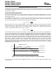
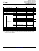
During the power save mode the output voltage is monitored with the comparator by the thresholds comp low
and comp high. As the output voltage falls below the comp low threshold set to typically 0.8% above Vout
nominal, the P-channel switch turns on. The P-channel switch is turned off as the peak switch current is
reached. The typical peak switch current can be calculated:
The N-channel rectifier is turned on and the inductor current ramps down. As the inductor current approaches
zero the N-channel rectifier is turned off and the P-channel switch is turned on again, starting the next pulse.
The converter continues these pulses until the comp high threshold (set to typically 1.6% above Vout nominal) is
reached. The converter enters a sleep mode, reducing the quiescent current to a minimum. The converter
wakes up again as the output voltage falls below the comp low threshold again. This control method reduces the
quiescent current typically to 15 µA and reduces the switching frequency to a minimum, thereby achieving the
high converter efficiency. Setting the skip current thresholds to typically 0.8% and 1.6% above the nominal
output voltage at light load current results in a dynamic output voltage achieving lower absolute voltage drops
during heavy load transient changes. This allows the converter to operate with a small output capacitor of just 10
µF and still have a low absolute voltage drop during heavy load transient changes. Refer to Figure 2 for detailed
operation of the power save mode.
Figure 2. Power Save Mode Thresholds and Dynamic Voltage Positioning
The converter enters the fixed frequency PWM mode again as soon as the output voltage falls below the comp
low 2 threshold.
4
Submit Documentation Feedback