
Datasheet

User's Guide
SLVU455A–April 2011–Revised August 2012
TPS62730, TPS62733 Stepdown Converters With Bypass
Mode for Ultralow-Power Wireless Applications
This user’s guide describes the TPS62730 and TPS62733 evaluation module (EVM), how to perform a
stand-alone evaluation or interface with a host or system. The design of the converter is for delivery of up
to 100 mA of continuous current to the output. One can switch the converter into bypass mode by
grounding the ON/BYP pin, or the device switches automatically with the input voltage falling to the output
regulation voltage. The TPS62730 and TPS62733 have a fixed (regulated) output voltage of 2.1 V and
2.3 V, respectively.
Contents
1 Introduction .................................................................................................................. 2
2 Considerations With Evaluating the TPS62730 and TPS62733 ...................................................... 2
3 Performance Specification Summary ..................................................................................... 2
4 Test Summary ............................................................................................................... 2
4.1 Equipment ........................................................................................................... 3
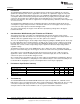
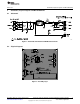
4.2 Equipment and EVM Setup ....................................................................................... 3
4.3 Test Procedure ..................................................................................................... 4
5 Schematic, Physical Layouts and Bill of Materials ..................................................................... 5
5.1 Schematic ........................................................................................................... 5
5.2 Physical Layouts ................................................................................................... 5
5.3 Bill of Materials ..................................................................................................... 7
6 Oscilloscope Traces (taken on the TPS62730EVM-726) .............................................................. 7
List of Figures
1 EVM Schematic and Evaluation Setup................................................................................... 3
2 TPS62730 and TPS62733 EVM Board Schematic..................................................................... 5
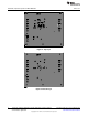
3 Assembly Layer ............................................................................................................. 5
4 Top Layer .................................................................................................................... 6
5 Bottom Layer ................................................................................................................ 6
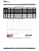
6 CH1: Phase; CH2: Output Ripple, Vin = 3.3 V, and 21-Ω Load ...................................................... 7
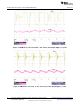
7 PFM Mode at Low Load, 40 mA – CH1: Phase; CH2: Output Ripple; 0.2 µs/div .................................. 8
8 PFM Mode at Low Load, 11 mA – CH1: Phase; CH2: Output Ripple; 1 µs/div .................................... 8
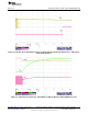
9 Transition From Switching Converter to Bypass Mode by Removing Input Power – CH1: Phase Node;
CH2: STAT Pin.............................................................................................................. 9
10 Transition From Converter Switch Mode to Bypass Mode by Pulling ON/BYP Pin Low .......................... 9
11 Transition From Bypass Mode to Converter Switch Mode by Pulling ON/BYP Pin High ........................ 10
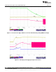
12 Start-Up by Hot-Plugging the Input Power Source.................................................................... 10
13 Transient Output Load Step From 50 mA to 100 mA................................................................. 11
14 Transient Output Load Step From 100 mA to 50 mA................................................................. 11
1
SLVU455A–April 2011–Revised August 2012 TPS62730, TPS62733 Stepdown Converters With Bypass Mode for Ultralow-
Power Wireless Applications
Submit Documentation Feedback
Copyright © 2011–2012, Texas Instruments Incorporated