
Datasheet

Setup and Results
www.ti.com
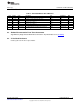
1.2 Performance Specification
Table 1 provides a summary of the TPS63036EVM-163 performance specifications. All specifications are
given for an ambient temperature of 25°C.
Table 1. Performance Specification Summary
Specification Test Conditions Min Typ Max Unit
Input voltage 1.8 5.5 V
Output voltage Vin = 4.2 V, Iout = 500 mA 3.2 3.3 3.4 V
Output current Vin = 3.6 V 0 600 mA
Operating frequency 2000 kHz
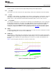
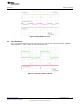
Efficiency 3.6 V in at 500-mA load 85%
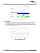
Output ripple 3.6 V in at 500-mA load 25 mV
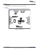
1.3 Modifications
The printed-circuit board (PCB) for this EVM is designed to accommodate both the fixed and adjustable
versions of this integrated circuit (IC). If the fixed version is installed, R1 is replaced with a 0-Ω resistor
and R2 is open.
1.3.1 Adjustable Output IC U1 Operation
U1 is configured for evaluation of the adjustable output version. This unit is configured for 3.3-V. Resistors
R1 and R2 are used to set the output voltage between 1.2-V and 5.5-V. See the TPS63036 data sheet
(SLVSB76) for recommended values.
1.3.2 Fixed Output Operation
U1 can be replaced with the fixed version for evaluation. R1 must be replaced with a 0-Ω resistor; the R2
position is open.
2 Setup and Results
This section describes how to properly use the TPS63036EVM-163.
2.1 Input / Output Connector and Header Descriptions
2.1.1 J1 – VIN
This header is the positive connection to the input power supply. The power supply must be connected
between J1 and J3 (GND). The leads to the input supply should be twisted and kept as short as possible.
The input voltage has to be between 1.8-V and 5.5-V.
2.1.2 J2 – VIN Sense/GND Sense
Header J2 can be used to measure the input voltage directly on the input capacitor. Therefore a 4-wire
power & sense supply can be connected. The leads to the sensing connector should also be twisted.
2.1.3 J3 – GND
This header is the return connection to the input power supply. Connect the power supply between J3 and
J1 (VIN). The leads to the input supply should be twisted and kept as short as possible. The input voltage
has to be between 1.8-V and 5.5-V.
2.1.4 J4 – VOUT
This header is the positive connection of the output voltage. The load has to be connected between J4
and J6 (GND).
2
TPS63036EVM-163 SLVU752–August 2012
Submit Documentation Feedback
Copyright © 2012, Texas Instruments Incorporated