
Computer Hardware User's Guide


www.ti.com
2.2 Setup
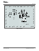
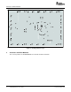
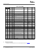
3 Board Layout
Board Layout
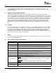
INPUT / OUTPUT DESCRIPTION
J11 – GND Return for VDCDC1
J12 – VDCDC2 Output from DCDC2 switching regulator, maximum output current 1 A, default voltage setting 2.5 V.
J13 – GND Return for VDCDC2
J14 – VLDO1 Output from the low drop out regulator VLDO1, maximun current out is 50 mA, default value 1.1 V.
J15 – GND Return for VLDO1
J16 –VLDO2 Output from the low drop out regulator, VLDO2 maximum current out is 50 mA, default value 1.3 V.
J17 – GND Return for VLDO2
J18 – VDCDC3 Output from the switching regulator DCDC3, maximum current is 800 mA, default value 1.55 A
J19 – GND Return for VDCDC3
J20 – USB USB interface connector
JP1 – DEF 1 Sets voltage for DCDC1 to 3 V or 3.3 V.
JP2 – DEF 2 Sets voltage for DCDC2 to 2.5 V or 1.8 V.
JP3 – DEF 3 Sets voltage for DCDC3 to 1.55 V or 1.3 V.
JP4 – DCDC1 ON/OFF EN for regulator DCDC1, default setting is ON.
JP5 – DCDC2 ON/OFF EN for regulator DCDC2, default setting is ON.
JP6 – DCDC3 ON/OFF EN for regulator DCDC3, default setting is ON.
JP7 – LDO ON/OFF EN for both LDO1 and LDO2 regulators, default setting is ON.
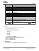
S1 is a normally open momentary push-button switch that, when pressed, connects V
I
to GPIO1.
S1 – GPIO1 The GPIO1 input is configured on the TPS65020 as a debounced push button that drives an
ON/OFF circuit with output at GPIO2.
S2 is a normally open momentary push-button switch that, when pressed, connects the HOT_RST
S2 – HOT_RST input of the TPS65020 to GND generating the Hot_Reset pulse. The HOT_RST pin is externally
pulled up.
The following steps must be followed before the EVM is operated
1. Install the TPS65020EVM Software.
2. Connect input voltages and loads to the EVM.
3. Configure all EVM jumpers to factory setting.
– JP4—ON
– JP1—3.3 V
– JP3—1.55 V
– JP2—2.5 V
– JP5—ON
– JP6—ON
– JP7—ON
4. Connect the Molex cable between the EVM and the EV2300. Note that the Molex cable must connect
to the I
2
C connector on the EV2300.
5. Connect the USB cable between the computer and the EVM.
6. Turn on all supplies and loads.
7. Run the TPS65020EVM software.
This section provides the TPS65020EVM-110 board layout and illustrations.
SLVU138 – August 2005 TPS65020EVM-110 User's Guide 3