
Datasheet

Test Point Descriptions
www.ti.com
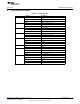
5 Test Point Descriptions
Table 2. Test Points
(1)(2)
Test Point Description
BAT Battery
AC AC adapter input
USB USB voltage input
nWAKEUP Wakeup output signal
MUXI Input to analog multiplexer
MUXO Output of analog multiplexer
DCDC1 DCDC1 output voltage
GND Ground
DCDC2 DCDC2 output voltage
GND Ground
PGOOD Power Good
SDA I2C Data
SCL I2C Clock
DCDC3 DCDC3 output voltage
nINT Interrupt Output
GND Ground
GND Ground
LDOPG LDO Power Good
(1)
Test points are not designed to carry current. They are intended for measuring voltage.
(2)
The test points for high current nodes (BAT, AC, USB, DCDC1, DCDC2, and DCDC3) are designed to
measure voltage at their respective input/output capacitor.
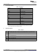
6 Jumper Descriptions
Table 3. Jumpers
Jumper Description
JP6 Connects battery to battery voltage sense input. User should only install this jumper if use of the battery charger is
desired and the supply connected to BAT is capable of sinking current.
JP9 Used to pull PWREN either high or low. If not installed, the software can control PWR_EN via the GPIO_PWR_EN
signal.
JP11 Connects TS input to a 10k resistor to simulate a thermistor. If using a battery pack, do not install this jumper. Instead,
use J4 to connect thermistor to TS.
JP18 Connects VIO to 3P3. Do not install if other VIO supply is desired.
JP39 Allows user to select input to LS1
JP42 Allows user to select input to LS2
ISINK1 Connects LED string to ISINK1. Must connect to use LEDs.
ISINK2 Connects LED string to ISINK2. Must connect to use LEDs.
6
TPS65217 EVM SLVU580B –November 2011–Revised June 2012
Submit Documentation Feedback
Copyright © 2011–2012, Texas Instruments Incorporated