
Datasheet

TPS7201Q, TPS7225Q, TPS7230Q
TPS7233Q, TPS7248Q, TPS7250Q, TPS72xxY
MICROPOWER LOW-DROPOUT (LDO) VOLTAGE REGULATORS
SLVS102G – MARCH 1995 – REVISED JUNE 2000
4
POST OFFICE BOX 655303 • DALLAS, TEXAS 75265
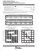
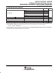
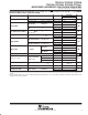
absolute maximum ratings over operating free-air temperature range (unless otherwise noted)
Input voltage range , V
I
, PG, SENSE, EN –0.3 V to 11 V. . . . . . . . . . . . . . . . . . . . . . . . . . . . . . . . . . . . . . . . . . . .
Output current, I
O
1.5 A. . . . . . . . . . . . . . . . . . . . . . . . . . . . . . . . . . . . . . . . . . . . . . . . . . . . . . . . . . . . . . . . . . . . . . . . .
Continuous total power dissipation See Dissipation Rating Tables 1 and 2. . . . . . . . . . . . . . . . . . . . . . . . . . . . .
Operating virtual junction temperature range, T
J
–55°C to 150°C. . . . . . . . . . . . . . . . . . . . . . . . . . . . . . . . . . . . .
Storage temperature range, T
stg
–65°C to 150°C. . . . . . . . . . . . . . . . . . . . . . . . . . . . . . . . . . . . . . . . . . . . . . . . . . .
Lead temperature 1,6 mm (1/16 inch) from case for 10 seconds 260°C. . . . . . . . . . . . . . . . . . . . . . . . . . . . . . .
†
Stresses beyond those listed under “absolute maximum ratings” may cause permanent damage to the device. These are stress ratings only, and
functional operation of the device at these or any other conditions beyond those indicated under “recommended operating conditions” is not
implied. Exposure to absolute-maximum-rated conditions for extended periods may affect device reliability.
‡
All voltage values are with respect to network ground terminal.
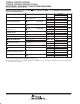
DISSIPATION RATING TABLE 1 – FREE-AIR TEMPERATURE (see Note 1 and Figure 3)
PACKAGE
T
A
≤ 25°C DERATING FACTOR T
A
= 70°C T
A
= 85°C T
A
= 125°C
PACKAGE
A
POWER RATING ABOVE T
A
= 25°C
A
POWER RATING
A
POWER RATING
A
POWER RATING
D
P
725 mW
1175 mW
5.8 mW/°C
8 74 mW/
°
C
464 mW
782 mW
377 mW
650 mW
145 mW
301 mW
P
PW
1175
mW
525 mW
8
.
74
mW/°C
4.2 mW/°C
782
mW
336 mW
650
mW
273 mW
301
mW
105 mW
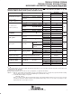
DISSIPATION RATING TABLE 2 – CASE TEMPERATURE (see Note 1 and Figure 4)
PACKAGE
T
C
≤ 25°C DERATING FACTOR T
C
= 70°C T
C
= 85°C T
C
= 125°C
PACKAGE
C
POWER RATING ABOVE T
C
= 25°C
C
POWER RATING
C
POWER RATING
C
POWER RATING
D
P
2063 mW
2738 mW
16.5 mW/°C
20 49 mW/
°
C
1320 mW
1816 mW
1073 mW
1508 mW
413 mW
689 mW
P
PW
2738
mW
2900 mW
20
.
49
mW/°C
23.2 mW/°C
1816
mW
1856 mW
1508
mW
1508 mW
689
mW
580 mW
NOTE 1: Dissipation rating tables and figures are provided for maintenance of junction temperature at or below absolute
maximum of 150°C. For guidelines on maintaining junction temperature within the recommended operating range,
see application information section.
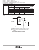
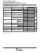
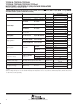
Figure 3
600
400
200
0
25 50 75 100
800
1000
1200
125 150
1100
900
700
500
300
100
– Maximum Continuous Dissipation – mW
MAXIMUM CONTINUOUS DISSIPATION
vs
FREE-AIR TEMPERATURE
P
D
T
A
– Free-Air Temperature – °C
D Package
R
θJA
= 172°C/W
PW Package
R
θJA
= 238°C/W
P Package
R
θJA
= 114.4°C/W
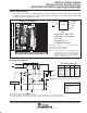
Figure 4
– Maximum Continuous Dissipation – mW
MAXIMUM CONTINUOUS DISSIPATION
vs
CASE TEMPERATURE
P
D
T
C
– Case Temperature – °C
1500
1000
500
0
25 50 75 100
2000
2500
3000
125 150
D Package
R
θJC
= 60.6°C/W
PW Package
R
θJC
= 43.1°C/W
P Package
R
θJC
= 48.8°C/W