
Datasheet

User's Guide
SLVU325 – August 2009
TPS727xxDSEEVM-406
This User’s Guide describes the characteristics, operation, and use of the TPS727xxDSEEVM-406. This
EVM demonstrates the Texas Instruments TPS727xx, a Low Drop Out (LDO) linear regulator in a 1,5 ×
1,5mm SON-6 package that is capable of 200mA of output current. This user’s guide includes setup
instructions, a schematic diagram, thermal guidelines, a bill of materials (BOM), and PCB layout drawings
for the evaluation module.
Contents
1 Introduction ................................................................................................................... 2
2 Setup .......................................................................................................................... 2
2.1 Input / Output Connector Descriptions ........................................................................... 2
3 Operation ..................................................................................................................... 2
3.1 Operation ............................................................................................................ 2
4 Thermal Guidelines .......................................................................................................... 3
4.1 Thermal Considerations ............................................................................................ 3
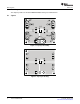
5 Board Layout ................................................................................................................. 4
5.1 Layout ................................................................................................................ 4
6 Schematic and Bill of Materials ............................................................................................ 6
6.1 Schematic ............................................................................................................ 6
6.2 Bill of Materials ...................................................................................................... 7
List of Figures
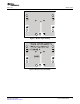
1 Top Layer Assembly ......................................................................................................... 4
2 Top Layer Routing ........................................................................................................... 4
3 Bottom Layer Routing ....................................................................................................... 5
4 Bottom Layer Assembly ..................................................................................................... 5
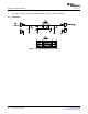
5 TPS727xxDSEEVM-406 Schematic ...................................................................................... 6
List of Tables
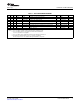
1 TPS727xxDSEEVM-406 BOM ............................................................................................ 7
SLVU325 – August 2009 TPS727xxDSEEVM-406 1
Submit Documentation Feedback