User’s Guide November 2001 Power Management Products Low Power SLVU062
IMPORTANT NOTICE Texas Instruments Incorporated and its subsidiaries (TI) reserve the right to make corrections, modifications, enhancements, improvements, and other changes to its products and services at any time and to discontinue any product or service without notice. Customers should obtain the latest relevant information before placing orders and should verify that such information is current and complete.
EVM IMPORTANT NOTICE Texas Instruments (TI) provides the enclosed product(s) under the following conditions: This evaluation kit being sold by TI is intended for use for ENGINEERING DEVELOPMENT OR EVALUATION PURPOSES ONLY and is not considered by TI to be fit for commercial use.
DYNAMIC WARNINGS AND RESTRICTIONS It is important to operate this EVM within the input voltage range of 2.8–5.5 V and the output current range of 0 mA to 5 mA. Exceeding the specified input range may cause unexpected operation and/or irreversible damage to the EVM. If there are questions concerning the input range, please contact a TI field representative prior to connecting the input power.
Preface About This Manual This user’s guide describes the TPS75525EVM LDO regulator evaluation module. Each EVM contains a SLVP190 test board with one TPS75525KTT 5-A, 2.5-V linear regulator and one TPS75733KTT 3-A, 3.3-V linear regulator as well as supporting passive components. The EVM provides a convenient method of evaluating the performance of the TPS755xx and TPS757xx linear regulator families.
vi
Running Title—Attribute Reference Contents 1 Introduction . . . . . . . . . . . . . . . . . . . . . . . . . . . . . . . . . . . . . . . . . . . . . . . . . . . . . . . . . . . . . . . . . . . . . 1.1 TPS755xx and TPS757xx Families of LDO Regulators . . . . . . . . . . . . . . . . . . . . . . . . . . 1.2 EVM Design Strategy . . . . . . . . . . . . . . . . . . . . . . . . . . . . . . . . . . . . . . . . . . . . . . . . . . . . . . . 1.3 Adjustment by Jumper and Switch . . . . . . . . . . . . . . . . . . . .
viii
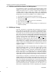
Chapter 1 Introduction This user’s guide describes the TPS75525EVM LDO regulator evaluation module. Each EVM contains an SLVP190 test board with one TPS75525KTT 5-A, 2.5-V linear regulator and one TPS75733KTT 3-A, 3.3-V linear regulator, as well as supporting passive components. Although other configurations are possible through jumper selection, this EVM is configured to perform power-up sequencing, i.e., the 2.5-V regulator powers up before the 3.3-V regulator.
TPS755xx and TPS757xx Families of LDO Regulators 1.1 TPS755xx and TPS757xx Families of LDO Regulators Like all LDO linear regulators, the TPS755xx and TPS757xx families of LDO regulators use a series pass element and feedback network, including an error amplifier and voltage reference, to provide a regulated output voltage from a slightly higher, possibly varying input voltage. The distinguishing characteristics of these regulators include high current output, low dropout and integrated power good.
Adjustment by Jumper and Switch 1.3 Adjustment by Jumper and Switch The schematic for the EVM is provided in Figure 1–1. Table 1–1. TPS75525EVM Jumper Explanations Jumper or Switch JP1 JP2 JP3 Status Description Open (Default) Pin 3 of JP3 is pulled high to VIN. If pins 2–3 of JP3 are shorted, then U2 EN is pulled high to VI thereby disabling U2. If pins 1–2 of JP3 are shorted, JP1 has no effect. Short Pin 3 of JP3 is tied low to GND.
1 2 1 + C1 100µ F R2 100k Ω R2 100k Ω 4 VIN VOUT EN FB/PG 5 C2 1µF C4 100µ F 1 TP6 FB/PG (core) 6 J2 3 GND 3 D1 TP8 GND 1 VIO MBRD835L 1 JP4 JP3 TP2 JP1 TP4 + U2 TPS75733KTT 2 1 VIN VOUT EN FB/PG C3 1µF 4 C5 100µ F 5 GND 6 TPS7 FB/PG IO R6 100k Ω 3 TP3 Introduction 1 R4, R5 for adj LDO only R5 1 1 V(core) 2 Schematic GND 2 U1 TPS75525KTT Figure 1-1 shows the TPS75525EVM schematic diagram. J1 V IN + R4 R3 100k Ω 1.4 Schematic TP5 Figure 1–1.
Bill of Materials 1.5 Bill of Materials Table 1–3 lists materials required for the TPS75525 EVMs. Table 1–3. TPS75525EVM Bill of Materials Qty Ref Des Description Size MFR Part Number 3 C1, C4, C5 Capacitor, tantalum, 100 µF, 10 V, 20% 7343 (D) Sprague 293D107X0010D2T 2 C2, C3 Capacitor, ceramic, 1-µF, 16 V, X7R, 10% 805 Murata GRM40X7R105K16 1 D1 Diode, Schottky, 8.
Board Layout Figure 1–3. Bottom Layer (top view) Figure 1–4.
Chapter 2 EVM Test Setup This chapter provides recommended test equipment and procedures for evaluating the power up sequencing capability of the TPS75525EVM. Figure 2–1 shows the test setup. Figure 2–1.
The following is a list of recommended equipment. - Power supply with 5-V and 8-A current limit connected to VI and GND. - Oscilloscope set to 100 µs/div and triggering off the falling edge of channel 1.
Chapter 3 Test Results This chapter presents laboratory test results of the TPS75525EVM obtained for the recommended test procedures in Chapter 2. Figure 3–1 shows the power up sequencing capability of the EVM. Channel 1 is ENABLE. Channel 2 is V(CORE). Channel 3 is VIO. Figure 3–1.
3-2 Test Results