
Datasheet

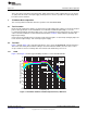
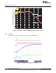
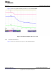
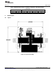
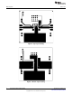
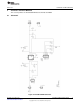
Table Of Contents

User's Guide
SLVU600–December 2011
TPS7A8101EVM Evaluation Module
This user’s guide describes the characteristics, operation, and use of the TPS7A8101EVM. This
evaluation module (EVM) demonstrates the Texas Instruments TPS7A8101 low-dropout (LDO) linear
regulator in a 3-mm x 3-mm, SON-8 package, which is capable of a 1-A output current. This user’s guide
includes setup instructions, a schematic diagram, thermal guidelines, a bill of materials, and printed-circuit
board layout drawings for the evaluation module.
Contents
1 Introduction .................................................................................................................. 2
2 Setup ......................................................................................................................... 2
2.1 Input/Output Connector Descriptions ............................................................................ 2
3 TPS7A8101 Device Operation ............................................................................................ 3
3.1 Test Procedure ..................................................................................................... 3
3.2 Test Data ............................................................................................................ 3
4 Thermal Guidelines ......................................................................................................... 6
4.1 Thermal Considerations ........................................................................................... 6
5 Board Layout ................................................................................................................ 7
5.1 Layout ............................................................................................................... 7
6 Schematic and Bill of Materials ........................................................................................... 9
6.1 Schematic ........................................................................................................... 9
6.2 Bill of Materials .................................................................................................... 10
List of Figures
1 TPS7A8101 PSRR for Variable Output Currents, VDO=0.7 V........................................................ 3
2 TPS7A8101 PSRR for Variable Dropout Voltage, Iout=1 A........................................................... 4
3 TPS7A8101 Start-Up Into Full Load, 1 A ................................................................................ 4
4 TPS7A8101 Shutdown with 3.3-Ω Load ................................................................................. 5
5 TPS7A8101 Transient Response ......................................................................................... 6
6 Top Layer Assembly........................................................................................................ 7
7 Top Layer Routing .......................................................................................................... 8
8 Bottom Layer Routing ...................................................................................................... 8
9 TPS7A8101EVM Schematic............................................................................................... 9
List of Tables
1 Maximum Input Voltage vs Ambient Temperature and Output Voltage ............................................. 6
2 Bill of Materials............................................................................................................. 10
1
SLVU600– December 2011 TPS7A8101EVM Evaluation Module
Submit Documentation Feedback
Copyright © 2011, Texas Instruments Incorporated