
TRF1500 Integrated Dual-Band RF Receiver User's Guide


SWRA004A
TRF1500 Integrated Dual-Band RF Receiver User’s Guide 59
High-Band Transmit Mixer Test Guide
This section involves measuring the High Band Transmit Mixer
performance. All tests apply for an IF output terminated into a 1
k
Ω
differential load. To match the IF output to the 50
Ω
test
equipment a transformer balun is used. All unused ports are
terminated into 50
Ω
. Testing the performance of the high transmit
mixer can be performed two ways. One being the LO Doubler
driven, no EVM modification needed. Two LO is directly driven,
before measuring the high band transmit mixer performance the
EVM board must be modified as follows: Remove L40 and C41,
add C24. This enables the high band transmit to be directly driven
by an LO source.
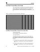
Table 6. High-Band Transmit Mixer Performance Parameters
PARAMETERS Min Typ Max UNIT
Tx Mixer Input Frequency 1850 1880 1910 MHz
LO Frequency Directly Driven 1733 1763 1793 MHz
LO Frequency Doubler Driven 983.5 998.5 1013.5 MHz
Tx Mixer Output Frequency 117 MHz
LO Input Power -5.0 dBm
RF Input Power -30 dBm
Power Conversion Gain 9.9 dB
Noise Figure 12.7 dB
RF Input Return Loss 16.6 dB
Power Leakage Tx In to LO In -55.5 dB
Power Leakage LO In to Tx In -69.5 dB
1dB Input Compression Point -15.7 dBm
Second Order Input Intercept point (IIP2) 27 dBm
Third Order Input Intercept Point(IIP3) -6.7 dBm
To test the High Band Transmit Mixer parameters use the
procedure for the Low Band Transmit Mixer, with the following
exception: Control state mode 110100 and when testing the Third
order intercept point the RF signal separation is 120kHz.