
User's Manual


TI PROPRIETARY T E X A S I N S T R U M E N T S
INFORMATION -
Revision:
INTERNAL DATA R F I D SYSTEMS 0
S P E C I F I C A T I O N
Page 13 of 25
xx-xx-xx-xxx
Printed copies are not controlled documents - verify the correct revision before use.
13. Antenna Tuning Details
Module antenna as shipped is tuned for 50Ω impedance at 13.56MHz. It has a
nominal bandwidth of 1.3MHz, which results in a quality factor of
approximately 10. Module antenna circuit has a board mounted U.FL
connector installed for users that want to experiment with different tuning
solutions or disconnect onboard antenna and experiment with antennas of their
own design or application. Below are some design/application notes for users
to reference if they want to change the antenna Q factor or experiment further
on their own in order to serve their particular application directly.
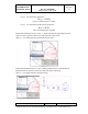
TRF79x0ATB coil antenna tuning details starts with calculations to produce
the theoretical values shown below (and based on measurements of antenna
coil on Rev B board.) Coil value nominally measures 0.95uH at 13.56MHz
and
X
L
= 0.8 + j80.8 = 0.990 @ 63.4°.
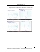
To calculate the necessary values required for course resonance tuning and
proper Q setting of the antenna, the following formula is used.
L
C
totalRES
2
)(
1
where ω = 2πf
therefore;
HMHz
C
totalRES
95.0)56.132(
1
2
)(
pFC
totalRES
157.145
)(
The dampening resistor value can now be calculated for a desired Q value
using the formula
fL
R
Q
PAR
2
therefore;
fLQR
PAR
2