
User's Manual

TI PROPRIETARY T E X A S I N S T R U M E N T S
INFORMATION -
Revision:
INTERNAL DATA R F I D SYSTEMS 0
S P E C I F I C A T I O N
Page 6 of 25
xx-xx-xx-xxx
Printed copies are not controlled documents - verify the correct revision before use.
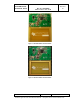
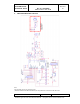
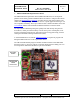
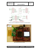
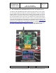
5. TRF79x0ATB Connections/Technical Details
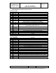
Connector P1/RF1
Pin # Signal Name Description
1 GND Ground
2 n/c
3 MOD Direct mode, external modulation input
4 n/c
5 n/c
6 n/c
7 IRQ Interrupt request (from TRF79x0A to MCU)
8 n/c
9 SYS_CLK
Clock for MCU (optional)
If EN = 0 and EN2 = 1, then system clock is set to 60 kHz
10 EN Chip enable input (If EN = 0, then chip is in power-down mode).
11 n/c
12 EN2
Pulse enable and selection of power down mode. If EN2 is connected to VIN, then
VDD_X is active during power down to support the MCU. Pin can also be used for
pulse wake-up from power-down mode.
13 n/c
14
SLAVE
SELECT
Slave Select, I/O_4 (Active Low)
15 n/c
16 DATA_CLK Data Clock Input for MCU Communication (from MCU)
17 n/c
18 MOSI I/O_7, Master Out, Slave In (Data In from MCU)
19 GND Ground
20 MISO I/O_6, Master In, Slave Out (Data Out from TRF7960)
Connector P2/RF2
Pin # Signal Name Description
1 n/c
2 n/c
3 n/c
4 n/c
5 n/c
6 n/c
7 +3.3VDC IN +VDC in (to TPS61222DCKT for generation of +5VDC)
8 n/c
9 +3.3VDC IN +VDC in (to TPS61222DCKT for generation of +5VDC)
10 n/c
11 n/c
12 n/c
13 n/c
14 n/c
15 n/c
16 n/c
17 n/c
18 ASK/OOK
Direct mode, selection between ASK and OOK modulation (0 = ASK, 1 = OOK)
Also can be configured to provide the received analog signal output (ANA_OUT)
19 n/c
20 n/c