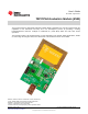
User's Guide SLOU321 – August 2011 TRF7970A Evaluation Module (EVM) The Texas Instruments TRF7970A evaluation module (EVM) is intended to be used by to demonstrate the capabilities of the TRF7970A and help aid in the development process by providing a working hardware/firmware reference example for traditional HF (13.56 MHz) RFID and also NFC Forum operations.
www.ti.com 1 2 3 4 Contents TRF7970A EVM Description .............................................................................................. 4 Using the TRF7970A EVM With PC GUI ................................................................................ 7 Abbreviations ............................................................................................................... 45 References ......................................................................................................
www.ti.com List of Tables 1 Logic Analyzer Connection Points on EVM at HDR_5 ................................................................. 5 2 Logic Analyzer Connection Points on EVM at HDR_1, HDR_3 and HDR_2 3 ISO/IEC 15693 Request Flags (b1 – b4) ................................................................................ 8 4 ISO/IEC 15693 Request Flags (b5 – b8) when Inventory Flag is NOT set 5 6 7 8 ....................................... .........................................
TRF7970A EVM Description 1 www.ti.com TRF7970A EVM Description The TRF7970A EVM features include: • Support for: – ISO15693 standard based transponders – ISO14443 standard based transponders (Types A and B) – NFC Forum modes (RFID reader\writer, peer to peer, and card emulation) • FeliCa™ based transponders (UID read only) • Standalone polling mode for quick demonstration of transponder detection • Communication with host software graphical user interface (GUI) via USB VCP The TRF7970A EVM also has the f
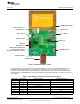
TRF7970A EVM Description www.ti.com PCB Magnetic Dipole Power and Protocol LED Indicators Resistor R3 J3 (SMA) Reset Switch MSP430F2370 TRF7970A MSP430 JTAG Interface MSP430F2370/TRF7970A Communication Header (default configuration shown) 13.56-MHz Crystal I/O_SEL Jumper USB Interface Figure 1.
TRF7970A EVM Description www.ti.com Table 2.
Using the TRF7970A EVM With PC GUI www.ti.com 2 Using the TRF7970A EVM With PC GUI 2.1 USB Driver The TRF7970A EVM has SiLabs CP2102 USB to UART Bridge IC onboard. The USB driver needs to be loaded onto the PC being used prior to attempting to start the TRF7970A EVM GUI. https://www.silabs.com/products/mcu/pages/USBtoUARTbridgeVCPdrivers.aspx 2.2 TRF7970A EVM GUI Startup The TRF7970A EVM GUI has a COM port auto detect function which is limited to COM ports 1 through 12.
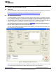
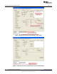
Using the TRF7970A EVM With PC GUI 2.3 www.ti.com ISO15693 Tab By default the TRF7970A EVM GUI starts up with the ISO15693 tab selected. The user should set/select the transponder/tag request flags as appropriate for the given operation (details on this to follow for each command) and by using the Set Protocol button in the GUI first before executing any commands so that the TRF7970A register settings match what is being sent out/expected back to/from the transponder(s) in the field of the EVM antenna.
Using the TRF7970A EVM With PC GUI www.ti.com 2.3.1 Inventory (Command Code 0x01) The ISO/IEC 15693 Inventory command is used to acquire the factory programmed and permanently locked 64 bit unique identifier(s) (UIDs) of transponders that are in within the read zone of the TRF7970A EVM antenna. They are used, as the name implies, to address each VICC uniquely and individually during the anticollision loop and for one to one exchange between a VCD and a VICC. The format of the UID is shown in Table 6.
Using the TRF7970A EVM With PC GUI www.ti.com Figure 3. Single Slot Inventory Command (One Tag in Field) Figure 4.
Using the TRF7970A EVM With PC GUI www.ti.com In time sensitive applications in which the number of tags that are presented to the field should be one at one time but could be from 1 to n, polling or looking for tags using the single slot method first might be effective. If a collision is detected, the firmware could then change the tag request flags to sixteen slot method and then proceed as described here. To 1. 2. 3. 4. 5.
Using the TRF7970A EVM With PC GUI www.ti.com NOTE: For graphics brevity, only five tags are shown. Figure 6.
Using the TRF7970A EVM With PC GUI www.ti.com 2.3.2 Read Single Block (Command Code 0x20) The Read Single Block Command is an optional command that requests one block of user memory data from a VICC, with the block number specified in the request. If the Option_flag is set in the request, the VICC also will return the block security status. This command can be sent as an addressed or unaddressed request. To 1. 2. 3. 4. 5. 6.
Using the TRF7970A EVM With PC GUI 2.3.3 www.ti.com Write Single Block (Command Code 0x21) The Write Single Block Command is an optional command that writes one block of user memory data on a VICC, with the block number and the block data specified in the request. For TI, TI based, and some other manufacturers' VICCs, the Option_flag must be set in the request.
Using the TRF7970A EVM With PC GUI www.ti.com 2.3.4 Lock Block (Command Code 0x22) The Lock Block Command is an optional command that locks one block of user memory data on a VICC, with the block number specified in the request. For TI, TI based, and some other manufacturers' VICCs, the Option_flag must be set in the request. This command can be sent as an addressed or unaddressed request, and the VICC returns an error/no error response after the lock operation has been completed. To 1. 2. 3. 4. 5. 6.
Using the TRF7970A EVM With PC GUI 2.3.5 www.ti.com Read Multiple Blocks (Command Code 0x23) The Read Multiple Blocks command is an optional command that requests more than one block of user memory data from a VICC at a time, with the first block number and the number of blocks specified in the request. This command can be sent as an addressed or unaddressed request. If the Option_flag is set in the request, the VICC also will return the block security status, followed by the block value, sequentially.
Using the TRF7970A EVM With PC GUI www.ti.com 2.3.6 Write Multiple Blocks (Command Code 0x24) This optional command is not currently known to be supported by any ISO/IEC 15693 transponders available. 2.3.7 Stay Quiet (Command Code 0x02) The Stay Quiet command is a mandatory command which instructs the VICC to enter the quiet state. The command is always issued as an addressed command and of course there is no response to the Stay Quiet Command.
Using the TRF7970A EVM With PC GUI 2.3.8 www.ti.com Select (Command Code 0x25) The Select command is an optional command that is always issued as an addressed command. If the UID sent as the address in the request matches the UID of the VICC, the VICC will enter the Selected state. The intention of the Select Command is that only one VICC in the field should be in the Selected state at any one time. To 1. 2. 3. 4. 5. 6.
Using the TRF7970A EVM With PC GUI www.ti.com 2.3.9 Reset to Ready (Command Code 0x26) The Reset to Ready Command is an optional command that returns the VICC(s) in the Quiet state to the Ready state. This command can be sent as an addressed or unaddressed request and the same end result can also be achieved by turning off the activating field from the VCD or removing the VICC(s) from the activating field. To 1. 2. 3. 4. 5.
Using the TRF7970A EVM With PC GUI 2.3.10 www.ti.com Write AFI (Command Code 0x27) The Write AFI Command is an optional command that writes a value to the AFI memory block on the VICC. For TI, TI based, and some other manufacturers' VICCs, the Option_flag must be set in the request. This command can be sent as an addressed or unaddressed request, and the VICC returns an error/no error response after the write operation has been completed. To 1. 2. 3. 4. 5. 6.
Using the TRF7970A EVM With PC GUI www.ti.com 2.3.11 Lock AFI (Command Code 0x28) The Lock AFI Command is an optional command that locks the value of the AFI memory block on the VICC. For TI, TI based, and some other manufacturers' VICCs, the Option_flag must be set in the request. This command can be sent as an addressed or unaddressed request, and the VICC returns an error/no error response after the lock operation has been completed. To 1. 2. 3. 4. 5.
Using the TRF7970A EVM With PC GUI 2.3.12 www.ti.com Write DSFID (Command Code 0x29) The Write DSFID Command is an optional command that writes a value to the DSFID memory block on the VICC. For TI, TI based, and some other manufacturers' VICCs, the Option_flag must be set in the request. This command can be sent as an addressed or unaddressed request, and the VICC returns an error/no error response after the write operation has been completed. To 1. 2. 3. 4. 5. 6.
Using the TRF7970A EVM With PC GUI www.ti.com 2.3.13 Lock DSFID (Command Code 0x2A) The Lock DSFID Command is an optional command that locks the value of the DSFID memory block on the VICC. For TI, TI based, and some other manufacturers' VICCs, the Option_flag must be set in the request. This command can be sent as an addressed or unaddressed request, and the VICC returns an error/no error response after the lock operation has been completed. To 1. 2. 3. 4. 5.
Using the TRF7970A EVM With PC GUI 2.3.14 www.ti.com Get System Information (Command Code 0x2B) The Get System Information Command is an optional command that retrieves the system information values from the VICC information fields. This command can be sent as addressed or unaddressed request. These fields are summary of what is and is not supported on the tag, what the user memory size of the VICC is, and if there is an IC reference field. The IC reference field is defined by the VICC IC manufacturer.
Using the TRF7970A EVM With PC GUI www.ti.com 2.3.15 Get Multiple Block Security Status (Command Code 0x2C) The Get Multiple Block Security Status Command is an optional command that retrieves the block security status on more than one block at a time, with the first block number and the number of blocks specified in the request. This command can be sent as addressed or unaddressed request. To 1. 2. 3. 4. 5. 6. 7.
Using the TRF7970A EVM With PC GUI 2.3.16 www.ti.com TI Custom Commands The TRF7970A supports the two custom commands that are outlined in the ISO/IEC 15693 standard and defined by Texas Instruments. The format outlined in the standard for custom VICC commands is shown in Table 7. These commands are only supported by TI "Plus" silicon based transponders, which can be identified by part numbers containing RI-xxx-112A. Table 7. Custom Commands Request Format SOF 2.3.16.
Using the TRF7970A EVM With PC GUI www.ti.com 2.4 ISO14443A Tab The ISO14443A tab is used to perform Layer 3 and some Layer 4 operations on ISO14443A PICCs, up to the stage at which transparent data is to be exchanged according to the ISO/IEC144443-4 standard. 2.4.1 Anticollision In the TRF7970A EVM GUI, this command performs the anticollision loop as outlined in the ISO/IEC14443-3 standard as outlined for one PICC (steps 1-5, flowchart for PCD).
Using the TRF7970A EVM With PC GUI www.ti.com Figure 21.
Using the TRF7970A EVM With PC GUI www.ti.com 2.4.2 Select, RATS, and PPS The Select command radio button is automatically selected after the anticollision loop is complete when using the ISO14443A tab, because this command cannot be issued to a PICC until the UID is obtained. To issue Select command, leave the PICC in the field and click Execute (see Figure 22). Figure 22.
Using the TRF7970A EVM With PC GUI www.ti.com Figure 23. RATS Command Example 2.4.3 HLTA and Deselect These commands are available in the GUI as needed to demonstrate stopping a card from responding while it remains in the field (HLTA) or to reset a card back to ready state once it has been selected (Deselect). Select the radio buttons as appropriate and click Execute.
Using the TRF7970A EVM With PC GUI www.ti.com 2.5 ISO14443B Tab The ISO14443B tab is used to perform Layer 3 and into Layer 4 operations on ISO14443B PICCs according to the ISO/IEC144443-4 standard. After selecting this tab, select the Set Protocol button. 2.5.1 Request (REQ_B) This command is used to probe the field for ISO/IEC14443B PICCs, and it retrieves the PUPI and other relevant information needed by the ATTRIB command (see Figure 24). Figure 24. REQ_B Command Example 2.5.
Using the TRF7970A EVM With PC GUI 2.5.3 www.ti.com ATTRIB This command is used to select an ISO14443B PICC and bring it into Layer 4. REQ_B should be sent before this command so that the TRF7970A system has the information that is required in this command (see Figure 25). Figure 25. ATTRIB Command Example 2.5.4 Halt This command is used to halt or stop a card from responding while still in the activation field.
Using the TRF7970A EVM With PC GUI www.ti.com 2.6 FeliCa Tab This tab is used to poll for FeliCa transponders. This transponder technology is from the Sony Corporation and is primarily used for payment, and it is also included in the NFC Forum specification, just like ISO/IEC 15693 and ISO/IEC 14443 transponders. 2.6.
Using the TRF7970A EVM With PC GUI www.ti.com Figure 27. Find Tags Tab Example 1 Figure 28.
Using the TRF7970A EVM With PC GUI www.ti.com 2.8 Registers Tab The Registers tab is used to retrieve the values in the TRF7970A registers and to directly change the values of those registers. Some of the register settings are coded in the TRF7970A EVM firmware for the various protocols commands; therefore, changes made in the Registers tab can be overwritten when going to a protocol tab and setting a different protocol.
Using the TRF7970A EVM With PC GUI www.ti.com Figure 30. Setting up TRF7970A EVM as Initiator 2.9.2 Target Setup To 1. 2. 3. set the second TRF7970A as a Target (Slave) (after connecting on the second PC) (see Figure 31): Click the NFC-PP tab. Check the Target Box in the Protocol Flags section of the GUI window. Click Set Protocol. Figure 31.
Using the TRF7970A EVM With PC GUI www.ti.com After setting up the two separate TRF7970A evaluation modules, they should be arranged in a parallel orientation relative to each other for the best coupling/best performance (see Figure 32). Figure 32.
Using the TRF7970A EVM With PC GUI 2.9.3 www.ti.com Peer-to-Peer Connection Step To connect the two TRF7970A evaluation modules (see Figure 33): 1. In the GUI for the Initiator, click Connect (the button then changes to Disconnect). 2. The Initiator and Target GUI indicators turn green when connection is successful. Not Connected (Initiator GUI) Connected (Initiator GUI) Figure 33. Peer-to-Peer Connection Step 2.9.
Using the TRF7970A EVM With PC GUI www.ti.com 2.9.5 NFC File Transfer While still in Initiator and Target modes as described in Section 2.9.3, files can also be transferred. This is done by selecting a file to be sent from the Initiator side and also a location (a file folder or directory) to store the file on the Target. Any file format can be transferred (for example, .doc, .xls, .jpg, or .zip). In this example, a firmware image file (.d43) is used. 1.
Using the TRF7970A EVM With PC GUI www.ti.com Initiator GUI File Transfer Being Started Initiator GUI File Transfer Complete Target File Folder Contents After File Transfer is Complete (File Received) Target GUI File Transfer in Progress Figure 37. NFC File Transfer Progress 2.9.6 Card Emulation Mode For card emulation mode, one TRF7970A EVM should be set up as a Target (see Section 2.9.2).
Using the TRF7970A EVM With PC GUI www.ti.com ISO14443A UID Read From TRF7970A in Card Emulation Mode ISO14443A Select Command Response From TRF7970A in Card Emulation Mode ISO14443A UID Read From TRF7970A in Card Emulation Mode ISO14443A Select Command Response From TRF7970A in Card Emulation Mode Figure 38. Card Emulation Mode 2.
Using the TRF7970A EVM With PC GUI www.ti.com Figure 39. Continuous Write to Registers 0x00 to 0x0B Example Figure 40.
Using the TRF7970A EVM With PC GUI www.ti.com 2. To turn on or off the MSP430F2370 GPIO-controlled LEDs on the EVM. These could also be used in the development environment for other functions such as turning on or off other peripherals, for digital control of reed relays and switches, etc. (see Table 8 and Figure 41). Table 8.
Using the TRF7970A EVM With PC GUI www.ti.com 3. To retrieve the PUPI from an ISO14443B tag on which anticollision has been disabled (this is most often the instance for ISO14443B cards that are being used for payment applications), thus requiring a single slot REQB to be sent. Notice in Figure 42 that the Send Raw button is used. This could have also been sent using the Send button with only B000 as the String to send. Figure 42.
Abbreviations www.ti.com 3 Abbreviations AFI BCC CRC DSFID EOF LSB MSB RFU SOF UID PCD PICC PUPI VCD VICC 4 Application Family Identifier Block Check Character Cyclic Redundancy Check Data Storage Format Identifier End of Frame Least Significant Byte Most Significant Byte Reserved for Future Use Start of Frame Unique Identifier Proximity Coupling Device Proximity Integrated Circuit Card Pseudo Unique PICC Identifier Vicinity Coupling Device Vicinity Integrated Circuit Card References 1.
IMPORTANT NOTICE Texas Instruments Incorporated and its subsidiaries (TI) reserve the right to make corrections, modifications, enhancements, improvements, and other changes to its products and services at any time and to discontinue any product or service without notice. Customers should obtain the latest relevant information before placing orders and should verify that such information is current and complete.
EVALUATION BOARD/KIT/MODULE (EVM) ADDITIONAL TERMS Texas Instruments (TI) provides the enclosed Evaluation Board/Kit/Module (EVM) under the following conditions: The user assumes all responsibility and liability for proper and safe handling of the goods. Further, the user indemnifies TI from all claims arising from the handling or use of the goods.
For EVMs annotated as FCC – FEDERAL COMMUNICATIONS COMMISSION Part 15 Compliant Caution This device complies with part 15 of the FCC Rules. Operation is subject to the following two conditions: (1) This device may not cause harmful interference, and (2) this device must accept any interference received, including interference that may cause undesired operation. Changes or modifications not expressly approved by the party responsible for compliance could void the user's authority to operate the equipment.
For EVMs annotated as IC – INDUSTRY CANADA Compliant This Class A or B digital apparatus complies with Canadian ICES-003. Changes or modifications not expressly approved by the party responsible for compliance could void the user’s authority to operate the equipment. Concerning EVMs including radio transmitters This device complies with Industry Canada licence-exempt RSS standard(s).
【Important Notice for Users of this Product in Japan】 This development kit is NOT certified as Confirming to Technical Regulations of Radio Law of Japan! If you use this product in Japan, you are required by Radio Law of Japan to follow the instructions below with respect to this product: (1) Use this product in a shielded room or any other test facility as defined in the notification #173 issued by Ministry of Internal Affairs and Communications on March 28, 2006, based on Sub-section 1.
EVALUATION BOARD/KIT/MODULE (EVM) WARNINGS, RESTRICTIONS AND DISCLAIMERS For Feasibility Evaluation Only, in Laboratory/Development Environments. Unless otherwise indicated, this EVM is not a finished electrical equipment and not intended for consumer use.