TUSB3210 Generic Evaluation Board User’s Guide 2005 MSP USB SLLU031A
IMPORTANT NOTICE Texas Instruments Incorporated and its subsidiaries (TI) reserve the right to make corrections, modifications, enhancements, improvements, and other changes to its products and services at any time and to discontinue any product or service without notice. Customers should obtain the latest relevant information before placing orders and should verify that such information is current and complete.
EVM IMPORTANT NOTICE Texas Instruments (TI) provides the enclosed product(s) under the following conditions: This evaluation kit being sold by TI is intended for use for ENGINEERING DEVELOPMENT OR EVALUATION PURPOSES ONLY and is not considered by TI to be fit for commercial use.
EVM WARNINGS AND RESTRICTIONS It is important to operate this EVM within the input voltage range of 4 V to 6 V and the output voltage range of 3 V to 3.6 V. Exceeding the specified input range may cause unexpected operation and/or irreversible damage to the EVM. If there are questions concerning the input range, please contact a TI field representative prior to connecting the input power.
Related Documentation From Texas Instruments Preface Read This First About This Manual This user’s guide describes the setup and operation of the TUSB3210 generic evaluation board. Familiarity with universal serial bus (USB) protocol and common laboratory testing equipment is required and assumed throughout this user’s guide.
Trademarks Trademarks MacOS is a trademark of Apple Computer, Inc. Windows and Windows ME are trademarks of Microsoft Corporation. Other trademarks are the property of their respective owners FCC Warning This equipment is intended for use in a laboratory test environment only.
Contents Contents 1 Hardware and Software Required . . . . . . . . . . . . . . . . . . . . . . . . . . . . . . . . . . . . . . . . . . . . . . . . 1.1 Equipment . . . . . . . . . . . . . . . . . . . . . . . . . . . . . . . . . . . . . . . . . . . . . . . . . . . . . . . . . . . . . . . . 1.2 Hardware Overview . . . . . . . . . . . . . . . . . . . . . . . . . . . . . . . . . . . . . . . . . . . . . . . . . . . . . . . . 1.3 Bill of Materials . . . . . . . . . . . . . . . . . . . . . . . . . . . . . . . . .
viii
Chapter 1 Hardware and Software Required The TUSB3210 generic EVM is designed for use with a personal computer running a USB-enabled operating system. The PC should be USB 1.1 specification compliant. This implies that the BIOS, chipsets, and operating system are all USB 1.1 specification compliant. If the BIOS is not specification compliant, the system may not boot up when USB devices are connected at power up, and the EVM may not function.
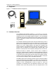
Running Title—Attribute Reference 1.1 Equipment Figure 1−1. TUSB3210 Evaluation Equipment USB EVM 1.2 Hardware Overview The TUSB3210 EVM hardware platform is 11 cm wide by 13 cm long. Throughout this document, text inside of parenthesis (ex.) denotes reference designators found on the TUSB3210 EVM. See Figure 1−2 for a photograph of the EVM. All jumpers are installed with the factory settings. See the jumper table for a description of settings, and make any required adjustments before using the EVM.
Running Title—Attribute Reference TUSB3210 device. A USB cable should be plugged into a USB port on a PC or into a USB hub and connected to the TUSB3210 EVM type-B connector (U3). Figure 1−2. TUSB3210 Evaluation Board Figure 1−3.
Running Title—Attribute Reference Figure 1−4. TUSB3210 Printed-Circuit Board (REV 1.
Running Title—Attribute Reference Figure 1−5. TUSB3210 Printed-Circuit Board (REV 1.
Running Title—Attribute Reference 1.3 Bill of Materials Item Quantity Reference Part 1 3 (REV 1.1 board) C1, C4, C10 Capacitor, 0.1 µF 1 7 (REV 1.2 board) C1, C4, C9, C10, C12, C13, C14 Capacitor, 0.1 µF 2 2 C2, C5 Capacitor, 4.7 µF 3 1 C3 Capacitor, 10 µF 4 3 C6, C7, C8 Capacitor, 22 pF 5 5 (REV 1.1 board) C9, C11, C12, C13, C14 Capacitor, 1 µF 5 1 (REV 1.
Running Title—Attribute Reference 1.4 Schematic Diagram The complete schematic diagram of the TUSB3210 generic EVM is presented at the end of this document.
1-8
Chapter 2 EVM Operation This chapter describes the operation of the TUSB3210 EVM. Topic Page 2.1 TUSB3210 Setup . . . . . . . . . . . . . . . . . . . . . . . . . . . . . . . . . . . . . . . . . . . . . . 2-2 2.2 Interfaces and USB Port . . . . . . . . . . . . . . . . . . . . . . . . . . . . . . . . . . . . . . . 2-2 2.3 Power Supplies . . . . . . . . . . . . . . . . . . . . . . . . . . . . . . . . . . . . . . . . . . . . . . . 2-2 2.4 Light Emitting Diodes (LEDs) . . . . . . . . . . . . . . . . .
Running Title—Attribute Reference 2.1 TUSB3210 Setup The TUSB3210 EVM supports many USB applications. The jumpers allow the flexibility to configure the EVM in various modes for evaluation purposes. Note that some modes require additional components not included with the EVM kit. The EVM comes in a default configuration that requires no additional components on the EVM. A full description of the TUSB3210 device is specified in the data manual (SLLS466).
Running Title—Attribute Reference 2.5 Jumpers and Switches Table 2−2 is provided to help set up and configure the EVM platform jumpers to the desired mode of operation. The EVM can download firmware code from the PC through a loading program (which may or may not be supplied with your EVM) or from an I2C EEPROM. A 5-V power source may be supplied from an external source or from the USB cable. If supplied from an external source, U2 must be set to position 2−3.
Running Title—Attribute Reference Figure 2−1. GPIO Connector JP1 1 3 5 7 9 11 13 15 17 19 21 23 25 27 29 31 33 35 37 39 41 43 45 47 49 2 P0.0 P0.1 4 P0.2 P0.3 6 P0.4 P0.5 8 P0.6 P0.7 10 P1.1 P1.0 P1.3 12 P1.2 P1.5 14 P1.4 P1.7 16 P1.6 18 P2.1 P2.0 P2.3 20 P2.2 22 P2.4 P2.5 24 P2.6 P2.7 26 P3.0 P3.1 P3.2 P3.3 28 30 P3.4 P3.5 32 P3.6 P3.7 34 S2 S3 36 PUR BS 38 SDA SCL1 SUSP 3.3 Susp 40 42 RST 1.8 V 3.3 V 3.
A B C D E TP4 +5V U1 C1 0.1uF JP(3) 1 100KR2 2 + OUT 5 1 2 2 C4 C2 GND 3 EN NC 2 1 SHORT 2 1 2 +1.8V 100K SHORT 4.7uF 4 1 [Wait 10ms before enable 3.3V] 2 2 1 Vbus 1 IN 1 2 1 1 C3 10uF 1 +5V U2 3 TP5 R18 S2 S1 4 TPS76333DBV 3 0.1uF C 1 R3 100k 1 2 1 4 BS 1 2 AC adaptor 5VDC 2 J1 +3.3V 1 TP3 2 C5 4.7uF 1 E 2 MMBT4401 NPN Q1 PUR 3 1 1 Type B USB-Shield CON1 +5V 1 6 DM 2 G2 1 GND 3 SUSP 16 SUSP 1 2 100K R8 +1.
A B C D E TP4 +5V U1 C1 0.1uF JP(3) R2 1 + 2 100K 5 OUT 1 GND 3 EN 2 1 2 1 +1.8V 4 0.1uF R3 100k 1 2 1 1 2 100K SHORT 4.7uF 4 NC SHORT C2 TPS76333DBV C 2 3 C4 2 TP5 R18 S2 1 IN 2 [Wait 10ms before enable 3.3V] 2 S1 1 C3 10uF 1 Vbus 2 1 1 2 4 1 +5V U2 3 1 2 BS 1 +3.3V 1 TP3 Power adaptor 5VDC J1 2 C5 4.