TUSB7320, TUSB7340 USB 3.0 xHCI HOST CONTROLLER Data Manual PRODUCTION DATA information is current as of publication date. Products conform to specifications per the terms of the Texas Instruments standard warranty. Production processing does not necessarily include testing of all parameters.
TUSB7320, TUSB7340 SLLSE76E – MARCH 2011 – REVISED JULY 2011 www.ti.com Contents 1 2 3 4 2 INTRODUCTION ................................................................................................................. 13 .................................................................................................................... 13 ........................................................................................................ 13 OVERVIEW ..............................................
TUSB7320, TUSB7340 SLLSE76E – MARCH 2011 – REVISED JULY 2011 www.ti.com 5 .......................................................................... 40 ............................................................ 40 4.27 Power Management Data Register ..................................................................................... 41 4.28 MSI Capability ID Register ............................................................................................... 41 4.29 Next Item Pointer Register .....
TUSB7320, TUSB7340 SLLSE76E – MARCH 2011 – REVISED JULY 2011 6 4 www.ti.com .................................................................. 67 .................................................................................... 67 5.5 Uncorrectable Error Mask Register ..................................................................................... 68 5.6 Uncorrectable Error Severity Register .................................................................................. 69 5.
TUSB7320, TUSB7340 SLLSE76E – MARCH 2011 – REVISED JULY 2011 www.ti.com 7 8 9 10 11 .................................................. 94 ............................................... 94 6.6.5 xHCI Supported Protocol Port Register (USB 2.0) ......................................................... 95 6.6.6 xHCI Supported Protocol Capability Register (USB 3.0) .................................................. 95 6.6.7 xHCI Supported Protocol Name String Register (USB 3.0) ...........................
TUSB7320, TUSB7340 SLLSE76E – MARCH 2011 – REVISED JULY 2011 www.ti.com List of Figures 2-1 Typical Application ............................................................................................................... 14 2-2 TUSB7320 RKM Package (Top View)......................................................................................... 17 2-3 TUSB7340 RKM Package (Top View).........................................................................................
TUSB7320, TUSB7340 SLLSE76E – MARCH 2011 – REVISED JULY 2011 www.ti.com List of Tables 2-1 Package Information ............................................................................................................. 14 2-2 Clock and Reset Signals ........................................................................................................ 18 2-3 PCI Express Signals .............................................................................................................
TUSB7320, TUSB7340 SLLSE76E – MARCH 2011 – REVISED JULY 2011 www.ti.com 4-40 MSI Message Control Register Description................................................................................... 42 4-41 PCI Register 4Ch ................................................................................................................. 42 4-42 MSI Lower Message Address Register Description ......................................................................... 42 4-43 PCI Register 4Ch .........
TUSB7320, TUSB7340 SLLSE76E – MARCH 2011 – REVISED JULY 2011 www.ti.com 4-88 MSI-X Table Offset and BIR Register Description ........................................................................... 57 4-89 PCI Register C8h ................................................................................................................. 57 4-90 MSI-X PBA Offset and BIR Register Descriptions ........................................................................... 57 4-91 PCI Register D0h .......
TUSB7320, TUSB7340 SLLSE76E – MARCH 2011 – REVISED JULY 2011 www.ti.com 6-10 HC Structural Parameters 3 Description ...................................................................................... 78 6-11 HC Capability Register 10h ..................................................................................................... 78 6-12 HC Capability Parameters Description ........................................................................................
TUSB7320, TUSB7340 www.ti.com SLLSE76E – MARCH 2011 – REVISED JULY 2011 6-55 xHCI Extended Capabilities Register (xHCI Extended Capabilities Base + 00h) ........................................ 93 6-56 USB Legacy Support Capability Register Description ....................................................................... 93 6-57 xHCI Extended Capabilities Register (xHCI Extended Capabilities Base + 04h) ........................................ 93 6-58 .............................................
TUSB7320, TUSB7340 SLLSE76E – MARCH 2011 – REVISED JULY 2011 12 List of Tables www.ti.
TUSB7320, TUSB7340 SLLSE76E – MARCH 2011 – REVISED JULY 2011 www.ti.com USB 3.0 xHCI HOST CONTROLLER Check for Samples: TUSB7320, TUSB7340 1 INTRODUCTION 1.1 Features • USB 3.
TUSB7320, TUSB7340 SLLSE76E – MARCH 2011 – REVISED JULY 2011 2 OVERVIEW 2.1 Description www.ti.com The TUSB7320 supports up to two downstream ports. The TUSB7340 is a USB 3.0 xHCI compliant host controller that supports up to four downstream ports. Both parts are available in a pin-compatible 100-pin RKM package. For the remainder of this document, the name TUSB73x0 is used to reference both the TUSB7320 and the TUSB7340. Table 2-1. Package Information PART NO.
TUSB7320, TUSB7340 SLLSE76E – MARCH 2011 – REVISED JULY 2011 www.ti.com 2.2 Related Documents • • • • • • • • • • 2.3 Universal Serial Bus 2.0 Specification Universal Serial Bus 3.0 Specification eXtensible Host Controller Interface for Universal Serial Bus (xHCI), Revision 0.96 PCI Express Base Specification, Revision 2.1 PCI Express Card Electromechanical Specification, Revision 2.0 ExpressCard Standard, Release 2.0 PCI Express Mini Card Electromechanical Specification, Revision 1.
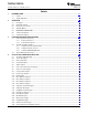
TUSB7320, TUSB7340 SLLSE76E – MARCH 2011 – REVISED JULY 2011 A39 A40 NC NC NC NC NC NC VDD11 NC JTAG_TCK NC VDD11 JTAG_TMS JTAG_TDO JTAG_RST# VDD33 PWRON1# JTAG_TDI PWRON2# OVERCUR1# WAKE# OVERCUR2# VDD11 B25 A25 VDDA_3P3 A24 R1EXT A23 XI A22 XO A21 VDDA_3P3 A20 USB_DP_DN1 A19 VDDA_3P3 A18 USB_SSRXP_DN1 VDD11 R1EXTRTN VDDA_3P3 VSS_OSC B21 VSS B20 VDD11 B19 B43 USB_DM_DN1 B18 A47 B44 VDD11 B17 A48 B45 USB_SSRXN_DN1 B16 A49 B46 A17 USB_SSTXP_DN1 A
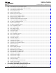
TUSB7320, TUSB7340 A40 VDD11 USB_DM_DN3 VDD11 USB_SSRXN_DN3 USB_SSTXN_DN3 USB_SSRXP_DN3 USB_SSTXP_DN3 NC VDD11 JTAG_TMS JTAG_TCK JTAG_TDO VDD11 JTAG_RST# VDD33 JTAG_TDI OVERCUR1# PWRON1# OVERCUR2# PWRON2# VDD11 USB_DP_DN3 B25 A26 B24 B38 B23 B39 B22 B40 B21 B41 B20 B42 B19 A20 B14 B48 B13 B12 VDD11 NC A14 NC A13 USB_DP_DN2 VDDA_3P3 A12 GRST# USB_DM_DN2 B11 A11 USB_SSTXN_DN2 USB_SSRXN_DN2 A10 USB_SSRXP_DN2 A9 NC A8 B10 USB_SSTXP_DN2 B9 VDD11 USB_SST
TUSB7320, TUSB7340 SLLSE76E – MARCH 2011 – REVISED JULY 2011 2.7 www.ti.com Terminal Descriptions The following tables give a description of the terminals. These terminals are grouped in tables by functionality. Each table includes the terminal name, terminal number, I/O type, and terminal description. TYPE DESCRIPTION I Input O Output I/O Input/Output PD, PU Internal pull-down/pull-up S Strapping pin P Power supply G Ground Table 2-2.
TUSB7320, TUSB7340 SLLSE76E – MARCH 2011 – REVISED JULY 2011 www.ti.com Table 2-4. USB Downstream Signals TERMINAL NAME TUSB7320 PIN NO. TUSB7340 PIN NO. I/O USB_SSTXP_ DN1 A17 A17 O USB SuperSpeed transmitter differential pair (positive). Note: When routing, it is permissible to swap the positive and negative signals in Port 1 SSTX differential pair. B15 B15 O USB SuperSpeed transmitter differential pair (negative).
TUSB7320, TUSB7340 SLLSE76E – MARCH 2011 – REVISED JULY 2011 www.ti.com Table 2-4. USB Downstream Signals (continued) TERMINAL I/O DESCRIPTION TUSB7320 PIN NO. TUSB7340 PIN NO. PWRON3# N/A A46 USB DS Port 3 Power On Control for Downstream Power. The terminal is used for O control of the downstream power switch. If the PWRON_POLARITY bit is set to ‘1’, this PD pin is active high and the internal pull-down is disabled. This pin may be at low impedance when power rails are removed.
TUSB7320, TUSB7340 SLLSE76E – MARCH 2011 – REVISED JULY 2011 www.ti.com Table 2-6. Test and Miscellaneous Signals (continued) TERMINAL NAME GPIO[0] GPIO[1] GPIO[2] GPIO[3] SMI R1EXT R1EXTRTN AUX_DET NC TUSB7320 PIN NO. TUSB7340 PIN NO. I/O A49, B46, B47, B48 A49, B46, B47, B48 I/O General purpose I/O PU B3 B3 O System management interrupt Note: This pin is active high and should not be pulled up/down. A24, B23 A24, B23 OI High precision external resistor used for calibration.
TUSB7320, TUSB7340 SLLSE76E – MARCH 2011 – REVISED JULY 2011 www.ti.com 3 FEATURE/PROTOCOL DESCRIPTIONS 3.1 Power-Up/-Down Sequencing The host controller contains both 1.1-V and 3.3-V power terminals. The following power-up and power-down sequences describe how power is applied to these terminals. In addition, the host controller has three resets: PERST#, GRST#, and an internal power- on reset. These resets are fully described in the next section.
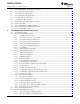
TUSB7320, TUSB7340 SLLSE76E – MARCH 2011 – REVISED JULY 2011 www.ti.com 3.1.2 Power-Down Sequence 1. Assert PERST# to the device. 2. Remove the reference clock. 3. Remove the 3.3-V and 1.1-V voltages See the power power-down sequencing diagram in Figure 3-2. If the VDD33_AUX terminal is to remain powered after a system shutdown, then the host controller power-down sequence is exactly the same as shown in Figure 3-2. VDD11 VDDA_3P3 and VDD33 PCIE_REFCLK PERST# Figure 3-2. Power-Down Sequence 3.
TUSB7320, TUSB7340 SLLSE76E – MARCH 2011 – REVISED JULY 2011 www.ti.com bidirectional. Both are open-drain signals and require pull-up resistors. The host controller is a bus master device and drives SCL at approximately 60 kHz during data transfers and places SCL in a high-impedance state (0 frequency) during bus idle states. The serial EEPROM is a bus slave device and must acknowledge a slave address equal to A0h. Figure 3-3 illustrates an example application implementing the two-wire serial bus.
TUSB7320, TUSB7340 SLLSE76E – MARCH 2011 – REVISED JULY 2011 www.ti.com 3.2.2 Serial-Bus Interface Protocol All data transfers are initiated by the serial-bus master. The beginning of a data transfer is indicated by a start condition, which is signaled when the SDA line transitions to the low state while SCL is in the high state, as illustrated in Figure 3-4.
TUSB7320, TUSB7340 SLLSE76E – MARCH 2011 – REVISED JULY 2011 www.ti.com Figure 3-6. Serial-Bus Protocal - Byte Write Figure 3-7 illustrates a single byte read. The host controller issues a start condition and sends the 7-bit slave device address and the R/W command bit is equal to 0b (write). The slave device acknowledges if it recognizes the slave address. Next, the EEPROM word address is sent by the host controller, and another slave acknowledgment is expected.
TUSB7320, TUSB7340 SLLSE76E – MARCH 2011 – REVISED JULY 2011 www.ti.com 3.2.3 Serial-Bus EEPROM Application A serial EEPROM interface is implemented to pre-load several registers. The registers and corresponding bits that are loaded through the EEPROM are provided in Table 3-1. Table 3-1.
TUSB7320, TUSB7340 SLLSE76E – MARCH 2011 – REVISED JULY 2011 3.3 www.ti.com System Management Interrupt The TUSB73X0 includes a System Management Interrupt (SMI) pin to allow for USB support in the BIOS of a system that implements the TUSB73X0. The SMI pin is controlled by the bits in the USB Legacy Support Control/Status Register. See Section 6.6.2 for more information. If there are no SMI events pending or if all sources for SMI are disabled, the TUSB73X0 drives the SMI pin low.
TUSB7320, TUSB7340 SLLSE76E – MARCH 2011 – REVISED JULY 2011 www.ti.com 4 CLASSIC PCI CONFIGURATION SPACE 4.1 The PCI Configuration Map The programming model of the TUSB73X0 USB 3.0 Host Controller is compliant to the standard PCI device programming model. The PCI configuration map uses the type 0 PCI header. All bits marked with a '*' are sticky bits and are reset by a global reset (GRST) or the internally-generated power-on reset.
TUSB7320, TUSB7340 SLLSE76E – MARCH 2011 – REVISED JULY 2011 www.ti.com Table 4-1. PCI Configuration Register Map (continued) MSI-X Message Control Next Item Pointer MSI-X CAP ID 0C0h MSI-X Table Offset and BIR 4.
TUSB7320, TUSB7340 SLLSE76E – MARCH 2011 – REVISED JULY 2011 www.ti.com 4.4 Command Register The Command register provides control over the TUSB73X0 interface to the PCIe interface PCI register offset: 04h Register type:Read-only, Read/Write Default value: 0000h Table 4-4. PCI Register 04h Bit No. 15 14 13 12 11 10 9 8 7 6 5 4 3 2 1 0 Reset State 0 0 0 0 0 0 0 0 0 0 0 0 0 0 0 0 Table 4-5.
TUSB7320, TUSB7340 SLLSE76E – MARCH 2011 – REVISED JULY 2011 4.5 www.ti.com Status Register The status register provides information about the PCI Express interface to the system. PCI register offset: 06h Register type:Read-only, Read/Clear Default value: 0010h Table 4-6. PCI Register 06h Bit No. 15 14 13 12 11 10 9 8 7 6 5 4 3 2 1 0 Reset State 0 0 0 0 0 0 0 0 0 0 0 0 0 0 0 0 Table 4-7.
TUSB7320, TUSB7340 SLLSE76E – MARCH 2011 – REVISED JULY 2011 www.ti.com 4.6 Class Code and Revision ID Register This read only register categorizes the Base Class, Sub Class, and Programming Interface of the TUSB73X0. The Base Class is 0Ch, identifying the device as a Serial Bus Controller. The Sub Class is 03h, identifying the function as a Universal Serial Bus Host Controller, and the Programming Interface is 30h, identifying the function as a USB 3.0 xHCI Host Controller.
TUSB7320, TUSB7340 SLLSE76E – MARCH 2011 – REVISED JULY 2011 4.8 www.ti.com Latency Timer Register This read-only register has no meaningful context for a PCI Express device and returns zeros when read. PCI register offset: 0Dh Register type:Read-only Default value: 00h Table 4-11. PCI Register 0Dh Bit No. 8 7 6 5 4 3 2 1 0 Reset State 0 0 0 0 0 0 0 0 0 4.9 Header Type Register This read only register indicates that this function has a type 0 PCI header.
TUSB7320, TUSB7340 SLLSE76E – MARCH 2011 – REVISED JULY 2011 www.ti.com 4.11 Base Address Register 0 This register is used to program the memory address used to access the device control registers. PCI register offset: 10h Register type:Read/Write,Read-only Default value: 0000 0004h Table 4-14. PCI Register 10h Bit No. 31 30 29 28 27 26 25 24 23 22 21 20 19 18 17 16 Reset State 0 0 0 0 0 0 0 0 0 0 0 0 0 0 0 0 Bit No.
TUSB7320, TUSB7340 SLLSE76E – MARCH 2011 – REVISED JULY 2011 www.ti.com 4.13 Base Address Register 2 This register is used to program the memory address used to access the MSI-X Table and PBA. PCI register offset: 18h Register type:Read/Write, Read-only Default value: 0000 0004h Table 4-18. PCI Register 18h Bit No. 31 30 29 28 27 26 25 24 23 22 21 20 19 18 17 16 Reset State 0 0 0 0 0 0 0 0 0 0 0 0 0 0 0 0 Bit No.
TUSB7320, TUSB7340 SLLSE76E – MARCH 2011 – REVISED JULY 2011 www.ti.com 4.15 Subsystem Vendor ID Register This register, which is used for system and option card identification purposes, may be required for certain operating systems. This read-only register is a direct reflection of the Subsystem Access register, which is read/write and is initialized through the EEPROM (if present) or can be written through the Subsystem Alias Register at PCI Offset D0h.
TUSB7320, TUSB7340 SLLSE76E – MARCH 2011 – REVISED JULY 2011 www.ti.com 4.18 Interrupt Line Register This read/write register is programmed by the system and indicates to the software which interrupt line the TUSB73X0 has been assigned. The default value of this register is FFh, indicating that an interrupt line has not yet been assigned to the function PCI register offset: 3Ch Register type:Read-only Default value: FFh Table 4-25. PCI Register 3Ch Bit No.
TUSB7320, TUSB7340 SLLSE76E – MARCH 2011 – REVISED JULY 2011 www.ti.com 4.22 Capability ID Register This read-only register identifies the linked list item as the register for PCI Power management. The register returns 01h when read. PCI register offset: 40h Register type:Read-only Default value: 01h Table 4-29. PCI Register 40h Bit No. 7 6 5 4 3 2 1 0 Reset State 0 0 0 0 0 0 0 1 4.
TUSB7320, TUSB7340 SLLSE76E – MARCH 2011 – REVISED JULY 2011 www.ti.com Table 4-32. Power Management Capabilities Register Description (continued) DSI r Device Specific Initialization. This bit returns 0 when read, indicating that the TUSB73X0 does not require special initialization beyond the standard PCI configuration header before a generic class driver is able to use it. 4 RSVD r Reserved. Returns zero when read. 3 PME_CLK r PME# Clock. 2:0 PM_VERSION r Power Mgmt Version.
TUSB7320, TUSB7340 SLLSE76E – MARCH 2011 – REVISED JULY 2011 www.ti.com 4.27 Power Management Data Register This read-only register is not applicable to the TUSB73X0 and returns 00h when read. PCI register offset: 47h Register type:Read-only Default value: 00h Table 4-36. PCI Register 47h Bit No. 7 6 5 4 3 2 1 0 Reset State 0 0 0 0 0 0 0 0 4.28 MSI Capability ID Register This read-only register identifies the linked list item as the register for Message Signaled Interrupts Capabilities.
TUSB7320, TUSB7340 SLLSE76E – MARCH 2011 – REVISED JULY 2011 www.ti.com Table 4-40. MSI Message Control Register Description Bit Field Name Access Description 15:8 RSVD r Reserved. Returns zeros when read. 8 PVM_CAP r Per-vector Masking Capable. This bit is read only 0 indicating that the TUSB73X0 does not support per-vector masking. 7 64CAP r 64 Bit Message Capability. This bit is read only 1 indicating that the TUSB73X0 supports 64 bit MSI message addressing.
TUSB7320, TUSB7340 SLLSE76E – MARCH 2011 – REVISED JULY 2011 www.ti.com 4.32 MSI Upper Message Address Register This register contains the upper 32 bits of the address that a MSI message is written to when an interrupt is to be signaled. If this register is 0000 0000h, 32-bit addressing is used; otherwise, 64-bit addressing is used. PCI register offset: 50h Register type:Read/Write Default value: 0000 0000h Table 4-43. PCI Register 4Ch Bit No.
TUSB7320, TUSB7340 SLLSE76E – MARCH 2011 – REVISED JULY 2011 www.ti.com 4.34 Serial Bus Release Number Register (SBRN) This read only register is set to 30h to indicate that the TUSB73X0 is compliant to release 3.0 of the Universal Serial Bus Specification. PCI register offset: 60h Register type:Read-only Default value: 00h Table 4-46. PCI Register 60h Bit No. 7 6 5 4 3 2 1 0 Reset State 0 0 1 1 0 0 0 0 4.
TUSB7320, TUSB7340 SLLSE76E – MARCH 2011 – REVISED JULY 2011 www.ti.com 4.37 Next Item Pointer Register The contents of this read-only register indicate the next item in the linked list of capabilities for the TUSB73X0. This register reads C0h pointing to the MSI-X Capability registers. PCI register offset: 71h Register type:Read-only Default value: C0h Table 4-50. PCI Register 71h Bit No. 7 6 5 4 3 2 1 0 Reset State 1 1 0 0 0 0 0 0 4.
TUSB7320, TUSB7340 SLLSE76E – MARCH 2011 – REVISED JULY 2011 www.ti.com 4.39 Device Capabilities Register The Device Capabilities Register indicates the device specific capabilities of the TUSB73X0. PCI register offset: 74h Register type:Read-only, Hardware Update Default value: 0000 8FC3h Table 4-53. PCI Register 74h Bit No. 31 30 29 28 27 26 25 24 23 22 21 20 19 18 17 16 Reset State 0 0 0 0 0 0 0 0 0 0 0 0 0 0 0 0 Bit No.
TUSB7320, TUSB7340 SLLSE76E – MARCH 2011 – REVISED JULY 2011 www.ti.com Table 4-54. Device Capabilities Register Description (continued) 2:0 MPSS Max Payload Size Supported. This field indicates the maximum payload size that the device can support for TLPs. This field is encoded as 011b indicating the Max Payload size for a TLP is 1 Kbyte. r 4.40 Device Control Register The Device Control Register controls PCI Express device specific parameters.
TUSB7320, TUSB7340 SLLSE76E – MARCH 2011 – REVISED JULY 2011 www.ti.com 4.41 Device Status Register The Device Status Register controls PCI Express device specific parameters. PCI register offset: 7Ah Register type:Read Only, Clear by a Write of One, Hardware Update Default value: 00x0h Table 4-57. PCI Register 7Ah Bit No. 15 14 13 12 11 10 9 8 7 6 5 4 3 2 1 0 Reset State 0 0 0 0 0 0 0 0 0 0 0 x 0 0 0 0 Table 4-58.
TUSB7320, TUSB7340 SLLSE76E – MARCH 2011 – REVISED JULY 2011 www.ti.com Table 4-60. Link Capabilities Register Description (continued) 18 CLK_PM r Clock Power Management. This bit is hardwired to 1 to indicate that the TUSB73X0 supports Clock Power Management through the CLKREQ# protocol. 17:15 L1_LATENCY r L1 Exit Latency. This field indicates the time that it takes to transition from the L1 state to the L0 state.
TUSB7320, TUSB7340 SLLSE76E – MARCH 2011 – REVISED JULY 2011 www.ti.com Table 4-62. Link Control Register Description (continued) 1:0 ASLPMC Active State Link PM Control. This field is used to enable and disable active state PM. 00 – Active State PM Disabled 01 – L0s Entry Enabled 10 – L1 Entry Enabled 11 – L0s and L1 Entry Enable rw 4.44 Link Status Register The Link Status Register indicates current state of the PCI Express Link.
TUSB7320, TUSB7340 SLLSE76E – MARCH 2011 – REVISED JULY 2011 www.ti.com Table 4-65. PCI Register 94h Bit No. 31 30 29 28 27 26 25 24 23 22 21 20 19 18 17 16 Reset State 0 0 0 0 0 0 0 0 0 0 0 0 0 0 0 0 Bit No. 15 14 13 12 11 10 9 8 7 6 5 4 3 2 1 0 Reset State 0 0 0 0 0 0 0 0 0 0 0 1 0 0 0 0 Table 4-66. Device Capabilities 2 Register Description Bit Field Name Access Description 31:5 RSVD r Reserved. Returns zeros when read.
TUSB7320, TUSB7340 SLLSE76E – MARCH 2011 – REVISED JULY 2011 www.ti.com Table 4-70. Link Control 2 Register Description Bit Field Name Access Description 15:13 RSVD r 12 COMPLIANCE_DEEMPH* rw Compliance De-Emphasis. This bit is sticky and is only reset by a Global Reset. 11 COMPLIANCE_SOS* rw Compliance SOS. This bit is sticky and is only reset by a Global Reset. 10 ENT_MOD_COMPLIANCE* rw Enter Modified Compliance. This bit is sticky and is only reset by a Global Reset.
TUSB7320, TUSB7340 SLLSE76E – MARCH 2011 – REVISED JULY 2011 www.ti.com 4.50 Serial Bus Index Register The value written to the Serial Bus Index register represents the byte address of the byte being read or written from the serial bus device. The Serial Bus Index register must be written before the before initiating a serial bus cycle by writing to the Serial Bus Slave Address register. This register is reset by a PCI Express reset (PERST#), a GRST#, or the internally-generated power-on reset.
TUSB7320, TUSB7340 SLLSE76E – MARCH 2011 – REVISED JULY 2011 www.ti.com Table 4-77. PCI Register B3h Bit No. 7 6 5 4 3 2 1 0 Reset State 0 0 0 0 0 0 0 0 Table 4-78. Serial Bus Control and Status Register Description (1) Bit Field Name Access 7† PROT_SEL† rw 6 RSVD r Reserved. Returns zero when read. 5† REQBUSY† r Requested Serial Bus Access Busy. This bit is set when a serial bus cycle is in progress.
TUSB7320, TUSB7340 SLLSE76E – MARCH 2011 – REVISED JULY 2011 www.ti.com Table 4-80. GPIO Control Register Description (1) (1) Bit Field Name Access Description 15:4 RSVD r 3† GPIO3_DIR† rw GPIO 3 Data Direction. This bit selects whether GPIO3 is in input or output mode. 0 – Input 1 – Output 2† GPIO2_DIR† rw GPIO 2 Data Direction. This bit selects whether GPIO2 is in input or output mode. 0 – Input 1 – Output 1† GPIO1_DIR† rw GPIO 1 Data Direction.
TUSB7320, TUSB7340 SLLSE76E – MARCH 2011 – REVISED JULY 2011 www.ti.com 4.55 MSI-X Capability ID Register This read-only register identifies the linked list item as the register for MSI-X Capabilities. The register returns 11h when read. PCI register offset: C0h Register type:Read-Only Default value: 11h Table 4-83. PCI Register C0h Bit No. 7 6 5 4 3 2 1 0 Reset State 0 0 0 1 0 0 0 1 4.
TUSB7320, TUSB7340 SLLSE76E – MARCH 2011 – REVISED JULY 2011 www.ti.com 4.58 MSI-X Table Offset and BIR Register This register indicates into which BAR and offset the MSI-X table is mapped. PCI register offset: C4h Register type:Read-Only Default value: 0000 0002h Table 4-87. PCI Register C4h Bit No. 31 30 29 28 27 26 25 24 23 22 21 20 19 18 17 16 Reset State 0 0 0 0 0 0 0 0 0 0 0 0 0 0 0 0 Bit No.
TUSB7320, TUSB7340 SLLSE76E – MARCH 2011 – REVISED JULY 2011 www.ti.com 4.60 Subsystem Access Register This register is a read/write register and the contents of this register are aliased to the Subsystem Vendor ID and Subsystem ID Registers at PCI Offsets 2Ch and 2Eh. This register is reset by a PCI Express reset (PERST#), a GRST#, or the internally-generated power-on reset. PCI register offset: D0h Register type:Read/Write Default value: 0000 0000h Table 4-91. PCI Register D0h Bit No.
TUSB7320, TUSB7340 SLLSE76E – MARCH 2011 – REVISED JULY 2011 www.ti.com Table 4-94. General Control 0 Register Description Bit Field Name Access Description 31:12 RSVD r 11:9† L1_EXIT_LAT_ASYNC† rw L1 Exit Latency for Asynchronous Clock. This value in this field is the value reported in the L1_LATENCY field in the Link Capabilities Register when the CCC bit in the Link Control Register is ‘0’. This field defaults to 110b. 8:6† L1_EXIT_LAT_COMMON† rw L1 Exit Latency for Common Clock.
TUSB7320, TUSB7340 SLLSE76E – MARCH 2011 – REVISED JULY 2011 www.ti.com 4.63 General Control 2 Register This register is a read/write register is used to control various functions of the TUSB73X0. This register is reset by a PCI Express reset (PERST#), a GRST#, or the internally-generated power-on reset. Note: For Pass 1.0 of the TUSB73X0 design, this register is read only zeros and has no effect. PCI register offset: DCh Register type:Read-Only,Read/Write Default value: 0000 001Bh Table 4-97.
TUSB7320, TUSB7340 SLLSE76E – MARCH 2011 – REVISED JULY 2011 www.ti.com Table 4-99. PCI Register E0h Bit No. 31 30 29 28 27 26 25 24 23 22 21 20 19 18 17 16 Reset State 0 0 0 0 0 0 0 0 0 0 0 0 0 0 0 0 Bit No. 15 14 13 12 11 10 9 8 7 6 5 4 3 2 1 0 Reset State 0 0 0 0 0 0 0 0 0 0 0 0 0 0 0 0 Table 4-100. USB Control Register Description (1) (2) Bit Field Name Access 31† USB_SPREAD_DIS† rw USB Spread Spectrum Disable.
TUSB7320, TUSB7340 SLLSE76E – MARCH 2011 – REVISED JULY 2011 www.ti.com Table 4-100. USB Control Register Description(1)(2) (continued) Bit Field Name Access Description 10† PORT3_DIS† rw USB Port 3 Disable. When this bit is set to ‘1’, port 3 of the TUSB73X0 is disabled. For the TUSB7320 Port 3 is not present and this bit has no effect. 9† PORT2_DIS† rw USB Port 2 Disable. When this bit is set to ‘1’, port 2 of the TUSB73X0 is disabled. 8† PORT1_DIS† rw USB Port 1 Disable.
TUSB7320, TUSB7340 SLLSE76E – MARCH 2011 – REVISED JULY 2011 www.ti.com Table 4-102. De-Emphasis and Swing Control Register Description (1) (1) Bit Field Name Access Description 31:28† PORT4_SWING† rw Port 4 Swing. When the PORT4_SWING_OV bit is set to ‘1’, these bits are used to set the output swing for port 4. For details on the behavior of the swing signals refer to Table 8-1. For the TUSB7320 Port 4 is not present and these bits have no effect. 27:24† PORT4_DE† rw Port 4 Deemphasis.
TUSB7320, TUSB7340 SLLSE76E – MARCH 2011 – REVISED JULY 2011 www.ti.com Table 4-104. Equalizer Control Register Description (1) Bit Field Name 31:28† PORT4_EQ_INIT† 27:24† PORT4_EQ_FUNC† 23:20† (1) PORT3_EQ_INIT† Access Description rw Port 4 Equalizer - Initialization Mode. When the PORT4_EQ_OV bit is set to ‘1’, these bits are used as the source for the Equalizer init values for port 4 of the PHY. For details on the behavior of the equalizer values refer to Table 8-3.
TUSB7320, TUSB7340 SLLSE76E – MARCH 2011 – REVISED JULY 2011 www.ti.com Table 4-106. Custom PHY Transmit/Receive Control Register Description (1) Bit Field Name Access 31:27 RSVD r 26† 25† (1) PORT4_EQ_OV† PORT4_SWING_OV† Description Reserved. Returns zeros when read. rw Port 4 Equalization Override.
TUSB7320, TUSB7340 SLLSE76E – MARCH 2011 – REVISED JULY 2011 www.ti.com 5 PCI EXPRESS EXTENDED CONFIGURATION SPACE 5.1 The PCI Express Extended Configuration Map Table 5-1.
TUSB7320, TUSB7340 SLLSE76E – MARCH 2011 – REVISED JULY 2011 www.ti.com 5.3 Next Capability Offset / Capability Version Register This read-only register identifies the next location in the PCI Express Extended Capabilities link list. The upper 12 bits in this register shall be 150h, indicating that the Device Serial Number Capability starts at offset 150h. The least significant four bits identify the revision of the current capability block as 2h.
TUSB7320, TUSB7340 SLLSE76E – MARCH 2011 – REVISED JULY 2011 www.ti.com Table 5-5. Custom PHY Transmit/Receive Control Register Description(1) (continued) 13† FC_ERROR † rcu Flow Control Error. This bit is asserted when a flow control protocol error is detected either during initialization or during normal operation. Poisoned TLP. This bit is asserted when a poisoned TLP is received. 12† PSN_TLP † rcu 11:5 RSVD r 4† DLL_ERROR † rcu 3:0 RSVD r 5.5 Reserved. Returns zeros when read.
TUSB7320, TUSB7340 SLLSE76E – MARCH 2011 – REVISED JULY 2011 www.ti.com Table 5-7. Bit Descriptions – Uncorrectable Error Mask Register(1) (continued) 13† FC_ERROR_MASK † rw Flow Control Error Mask. 0 – Error Condition is Unmasked 1 – Error Condition is Masked 12† PSN_TLP_MASK † rw Poisoned TLP Mask. 0 – Error Condition is Unmasked 1 – Error Condition is Masked 11:5 RSVD r 4† DLL_ERROR_MASK † rw 3:0 RSVD r 5.6 Reserved. Returns zeros when read. Data Link Protocol Error Mask.
TUSB7320, TUSB7340 SLLSE76E – MARCH 2011 – REVISED JULY 2011 www.ti.com Table 5-9. Bit Descriptions – Uncorrectable Error Severity Register(1) (continued) 15† CPL_ABORT_SEVR † rw Completer Abort Severity. 0 – Error Condition is signaled using ERR_NONFATAL 1 – Error Condition is signaled using ERR_FATAL 14† CPL_TIMEOUT_SEVR † rw Completion Timeout Severity.
TUSB7320, TUSB7340 SLLSE76E – MARCH 2011 – REVISED JULY 2011 www.ti.com Table 5-11. Bit Descriptions – Correctable Error Severity Register(1) (continued) RX_ERROR † 0† 5.8 Receiver Error. This bit is asserted when an 8b/10b error is detected by the PHY at any time. rcu correctable Error Mask Register The Correctable Error Status Register reports the status of individual errors as they occur. Software may clear these bits only by writing a 1 to the desired location.
TUSB7320, TUSB7340 SLLSE76E – MARCH 2011 – REVISED JULY 2011 5.9 www.ti.com Advanced Error Capabilities and control Register The Advanced Error Capabilities and Control Register allows the system to monitor and control the advanced error reporting capabilities. PCI Express Extended Register Offset: 118h Register type:Read-Only, Read/Write Default value: 0000 0050h Table 5-14. PCI Express Extended Register 118h Bit No.
TUSB7320, TUSB7340 SLLSE76E – MARCH 2011 – REVISED JULY 2011 www.ti.com 5.10 Header Log Register The Header Log Register stores the TLP header for the packet that lead to the most recently detected error condition. Offset 11Ch contains the first DWORD. Offset 128h contains the last DWORD (in the case of a 4DW TLP header. Each DWORD is stored with the least significant byte representing the earliest transmitted.
TUSB7320, TUSB7340 SLLSE76E – MARCH 2011 – REVISED JULY 2011 www.ti.com 5.13 Device Serial Number Register This read-only register identifies the Device Serial Number for the TUSB73x0. The Device Serial Number is in the format of an IEEE defined 64-bit extended unique identifier (EUI-64). The EUI-64 consists of TI’s 24-bit company ID (called an OUI-24) plus a 40 bit extension identifier. TI’s OUI-24 is 080028h and is hardwired into bits 63:40 of the Device Serial Number Register.
TUSB7320, TUSB7340 SLLSE76E – MARCH 2011 – REVISED JULY 2011 www.ti.com 6 xHCI MEMORY MAPPED REGISTER SPACE 6.1 The xHCI Register Map The TUSB73X0 includes xHCI registers in memory mapped register space. These registers are accessible via the address programmed into the Base Address Register 0/1. All bits marked with a ‘*’ are sticky bits and are only reset by a Global Reset (GRST#). Table 6-1. xHCI Register Map 6.
TUSB7320, TUSB7340 SLLSE76E – MARCH 2011 – REVISED JULY 2011 6.2.2 www.ti.com Host Controller Interface Version Number This read only register indicates the xHCI specification revision number supported by the TUSB73X0. BAR0 register offset: 02h Register type:Read-Only Default value: 0096h Table 6-4. HC Capability Register 02h Bit No. 15 14 13 12 11 10 9 8 7 6 5 4 3 2 1 0 Reset State 0 0 0 0 0 0 0 0 1 0 0 1 0 1 1 0 6.2.
TUSB7320, TUSB7340 SLLSE76E – MARCH 2011 – REVISED JULY 2011 www.ti.com 6.2.4 Host Controller Structural Parameters 2 This read only register defines basic structural parameters supported by the TUSB73X0. BAR0 register offset: 08h Register type:Read-Only Default value: 0C00 00F1h Table 6-7. HC Capability Register 08h Bit No. 31 30 29 28 27 26 25 24 23 22 21 20 19 18 17 16 Reset State 0 0 0 0 1 1 0 0 0 0 0 0 0 0 0 0 Bit No.
TUSB7320, TUSB7340 SLLSE76E – MARCH 2011 – REVISED JULY 2011 www.ti.com Table 6-10. HC Structural Parameters 3 Description Bit Field Name Access 31:16 U2_EXIT_LAT r U2 Device Exit Latency. This field is 07FFh to indicate that the worst case latency for the TUSB73X0 to transition from U2 to U0 is 2047 µs. 15:8 RSVD r Reserved. Returns zeros when read. 7:0 U1_EXIT_LAT r U1 Device Exit Latency.
TUSB7320, TUSB7340 SLLSE76E – MARCH 2011 – REVISED JULY 2011 www.ti.com Table 6-12. HC Capability Parameters Description (continued) 0 6.2.7 AC64 64-bit Addressing Capability. This bit is ‘1’ to indicate that the TUSB73X0 implements 64-bit address memory pointers. r Doorbell Offset This read only register returns 0000 05C0h when read to indicate that the beginning of the Doorbell Array is at an offset of 5C0h from the address programmed into the Base Address Register 0.
TUSB7320, TUSB7340 SLLSE76E – MARCH 2011 – REVISED JULY 2011 6.3 www.ti.com Host Controller Operational Registers These registers control the operation of the TUSB73X0. The offset in Table 6-15 is from the Operational Base, which is the address programmed into the Base Address Register 0 plus the value programmed into the Capability Registers Length (see Section 6.2.1). Table 6-15. Host Controller Operational Register Map 6.3.
TUSB7320, TUSB7340 SLLSE76E – MARCH 2011 – REVISED JULY 2011 www.ti.com 6.3.2 USB Command Register This register indicates the command to be executed by the TUSB73X0. Operational Base register offset:00h Register type:Read-Only,Read/Write Default value: 0000 0000h Table 6-17. HC Operational Register (Operational Base + 00h) Bit No. 31 30 29 28 27 26 25 24 23 22 21 20 19 18 17 16 Reset State 0 0 0 0 0 0 0 0 0 0 0 0 0 0 0 0 Bit No.
TUSB7320, TUSB7340 SLLSE76E – MARCH 2011 – REVISED JULY 2011 www.ti.com Table 6-20. USB Status Register Description Bit Field Name Access 31:13 RSVD r Reserved. Returns zeros when read. 12 HCE r Host Controller Error 11 CNR r Controller Not Ready 10 SRE rc Save/Restore Error. 9 RSS r Restore State Status. 8 SSS r Save State Status. 7:5 RSVD r Reserved. Returns zeros when read. 4 PCD rc Port Change Detect 3 EINT rc Event Interrupt. 2 HSE rc Host System Error.
TUSB7320, TUSB7340 SLLSE76E – MARCH 2011 – REVISED JULY 2011 www.ti.com 6.3.5 Device Notification Control Register This register is used by software to enable or disable the reporting of the reception of specific USB Device Notification Transaction Packets. Operational Base register offset:14h Register type:Read-Only, Read/Write Default value: 0000 0000h Table 6-23. HC Operational Register (Operational Base + 14h) Bit No.
TUSB7320, TUSB7340 SLLSE76E – MARCH 2011 – REVISED JULY 2011 www.ti.com Table 6-26. Command Ring Control Register Description Bit Field Name Access 31:6 COM_RING_POINT rw 5:4 RSVD r Reserved. Returns zeros when read. 3 CRR r Command Ring Running. 2 CA rw Command Abort. 1 CS rw Command Stop. 0 RCS rw Ring Cycle State. 6.3.7 Description Command Ring Pointer.
TUSB7320, TUSB7340 SLLSE76E – MARCH 2011 – REVISED JULY 2011 www.ti.com 6.3.8 Configure Register This register defines runtime xHC configuration parameters. Operational Base register offset:38h Register type:Read-Only, Read/Write Default value: 0000 0000h Table 6-29. HC Operational Register (Operational Base + 38h) Bit No. 31 30 29 28 27 26 25 24 23 22 21 20 19 18 17 16 Reset State 0 0 0 0 0 0 0 0 0 0 0 0 0 0 0 0 Bit No.
TUSB7320, TUSB7340 SLLSE76E – MARCH 2011 – REVISED JULY 2011 www.ti.com Table 6-32. Port Status and Control Register Description (continued) 26 WDE * rw Wake on Disconnect Enable. 25 WCE * rw Wake on Connect Enable. 24 RSVD r 23 CEC * rc or r 22 PLC * rc Port Link State Change. 21 PRC * rc Port Reset Change. 20 OCC * rc Over-current Change. 19 WRC * rc or r 18 PEC * rc Port Enabled/Disabled Change. 17 CSC * rc Connect Status Change.
TUSB7320, TUSB7340 SLLSE76E – MARCH 2011 – REVISED JULY 2011 www.ti.com 6.3.11 Port PM Status and Control Register (USB 2.0 Ports) The TUSB73X0 implements a Port PM Status and Control Register for each port that is implemented. The number of Port PM Status and Control Registers is the same as the value in the MAX_PORTS field in the Host Controller Structural Parameters 1 Register (see Section 6.2.3).
TUSB7320, TUSB7340 SLLSE76E – MARCH 2011 – REVISED JULY 2011 www.ti.com Table 6-38. Port Link Info Register Description Bit Field Name Access 31:16 RSVD r Reserved. Returns zeros when read. 15:0 LINK_ERROR_COUNT r Link Error Count. 6.4 Description Host Controller Runtime Registers These registers are used to read the current microframe and to control the interrupters of the TUSB73X0.
TUSB7320, TUSB7340 SLLSE76E – MARCH 2011 – REVISED JULY 2011 www.ti.com 6.4.2 Interrupter Management Register The TUSB73X0 implements 8 Interrupter Management Registers, one for each Interrupter implemented. Runtime Base register offset:20h + (20h*Interrupter), where Interrupter = 0 through 7 Register type:Read-Only,Read/Write Default value: 0000 0000h Table 6-42. HC Runtime Register (Runtime Base + 20h + (20h*Interrupter)), where Interrupter = 0 through 7 Bit No.
TUSB7320, TUSB7340 SLLSE76E – MARCH 2011 – REVISED JULY 2011 6.4.4 www.ti.com Event Ring Segment Table Size Register The TUSB73X0 implements 8 Event Ring Segment Table Size Registers, one for each Interrupter implemented. Runtime Base register offset:28h + (20h*Interrupter), where Interrupter = 0 through 7 Register type:Read-Only,Read/Write Default value: 0000 0000h Table 6-46. HC Runtime Register (Runtime Base + 28h + (20h*Interrupter)), where Interrupter = 0 through 7 Bit No.
TUSB7320, TUSB7340 SLLSE76E – MARCH 2011 – REVISED JULY 2011 www.ti.com Table 6-49. Event Ring Segment Table Base Address Register Description Bit Field Name Access 63:4 ERST_BASE rw 3:0 RSVD r 6.4.6 Description Event Ring Segment Table Base Address. Reserved. Returns zeros when read. Event Ring Dequeue Pointer Register The TUSB73X0 implements 8 Event Ring Dequeue Pointer Registers, one for each Interrupter implemented.
TUSB7320, TUSB7340 SLLSE76E – MARCH 2011 – REVISED JULY 2011 6.5 www.ti.com Host Controller Doorbell Registers The TUSB73X0 supports an array of 65 Doorbell Registers, one for the host controller plus one for each Device Slot supported. The address of the first Doorbell Register is the address programmed into the Base Address Register 0 plus the value programmed into the Doorbell Offset (see Section 6.2.7).
TUSB7320, TUSB7340 SLLSE76E – MARCH 2011 – REVISED JULY 2011 www.ti.com Table 6-55. xHCI Extended Capabilities Register (xHCI Extended Capabilities Base + 00h) Bit No. 31 30 29 28 27 26 25 24 23 22 21 20 19 18 17 16 Reset State 0 0 0 0 0 0 0 0 0 0 0 0 0 0 0 0 Bit No. 15 14 13 12 11 10 9 8 7 6 5 4 3 2 1 0 Reset State 0 0 0 0 0 1 0 0 0 0 0 0 0 0 0 1 Table 6-56.
TUSB7320, TUSB7340 SLLSE76E – MARCH 2011 – REVISED JULY 2011 www.ti.com Table 6-58. USB Legacy Support Control/Status Register Description (continued) 13 SMI_OS_EN rw 12:5 RSVD r 4 SMI_HOST_SYS_ERR_EN rw 3:1 RSVD r 0 USB_SMI_EN rw 6.6.3 SMI on OS Ownership Enable. Reserved. Returns zeros when read. SMI on Host System Error Enable. Reserved. Returns zeros when read. USB SMI Enable. xHCI Supported Protocol Capability Register (USB 2.
TUSB7320, TUSB7340 SLLSE76E – MARCH 2011 – REVISED JULY 2011 www.ti.com Table 6-61. xHCI Extended Capabilities Register (xHCI Extended Capabilities Base + 14h) Bit No. 31 30 29 28 27 26 25 24 23 22 21 20 19 18 17 16 Reset State 0 0 1 0 0 0 0 0 0 1 0 0 0 0 1 0 Bit No. 15 14 13 12 11 10 9 8 7 6 5 4 3 2 1 0 Reset State 0 1 0 1 0 0 1 1 0 1 0 1 0 1 0 1 6.6.5 xHCI Supported Protocol Port Register (USB 2.
TUSB7320, TUSB7340 SLLSE76E – MARCH 2011 – REVISED JULY 2011 www.ti.com Table 6-64. xHCI Extended Capabilities Register (xHCI Extended Capabilities Base + 20h) Bit No. 31 30 29 28 27 26 25 24 23 22 21 20 19 18 17 16 Reset State 0 0 0 0 0 0 1 1 0 0 0 0 0 0 0 0 Bit No. 15 14 13 12 11 10 9 8 7 6 5 4 3 2 1 0 Reset State 0 0 0 0 0 0 0 0 0 0 0 0 0 0 1 0 Table 6-65. xHCI Supported Protocol Capability Register (USB 3.
TUSB7320, TUSB7340 SLLSE76E – MARCH 2011 – REVISED JULY 2011 www.ti.com Table 6-67. xHCI Extended Capabilities Register (xHCI Extended Capabilities Base + 28h) Bit No. 31 30 29 28 27 26 25 24 23 22 21 20 19 18 17 16 Reset State 0 0 0 0 0 0 0 0 0 0 0 0 0 0 0 0 Bit No. 15 14 13 12 11 10 9 8 7 6 5 4 3 2 1 0 Reset State 0 0 0 0 0 x x 0 0 0 0 0 0 x x 1 Table 6-68. xHCI Supported Protocol Capability Register (USB 3.
TUSB7320, TUSB7340 SLLSE76E – MARCH 2011 – REVISED JULY 2011 www.ti.com 7 MSI-X MEMORY MAPPED REGISTER SPACE 7.1 The MSI-X Table and PBA in Memory Mapped Register Space The TUSB73X0 includes the MSI-X Table and PBA in memory mapped register space. These registers are accessible via the address programmed into the Base Address Register 2/3. Table 7-1.
TUSB7320, TUSB7340 SLLSE76E – MARCH 2011 – REVISED JULY 2011 www.ti.com 8 PHY CONTROL 8.1 Output Voltage Swing Control The output swing of each transmitter can be independently set to one of a number of settings via the SWING bits in the De-Emphasis and Swing Control Register, see Section 4.65. Reducing the output amplitude decreases the current drawn in direct proportion to the reduction in swing, thereby saving power. Table 8-1. Differential Output Swing Swing Value AC-Coupled Amplitude 0000 2.
TUSB7320, TUSB7340 SLLSE76E – MARCH 2011 – REVISED JULY 2011 8.2 www.ti.com De-Emphasis Control De-emphasis provides a means to compensate for high frequency attenuation in the attached media. It causes the output amplitude to be smaller for bits which are not preceded by a transition than for bits which are. Fifteen different de-emphasis settings are provided via the PORTx_DE bits in the De-Emphasis and Swing Control Register, see Section 4.65. Table 8-2. Differential Output De-Emphasis Value 8.
TUSB7320, TUSB7340 SLLSE76E – MARCH 2011 – REVISED JULY 2011 www.ti.com When enabled, the receiver equalization logic analyzes data patterns and transition times to determine whether the low frequency gain of the equalizer should be increased or decreased. For the fully adaptive setting (EQ = 0001), if the low frequency gain reaches the minimum value, the zero frequency is then reduced. Likewise, if it reaches the maximum value, the zero frequency is then increased.
TUSB7320, TUSB7340 SLLSE76E – MARCH 2011 – REVISED JULY 2011 www.ti.com 9 INPUT CLOCK 9.1 Clock Source Requirements The TUSB73x0 supports an external oscillator source or a crystal unit. The frequency of the clock source may be 20 MHz – 50 MHz. The FREQSEL pin is used to indicate the oscillator input frequency. If the FREQSEL pin is pulled low, the oscillator input frequency is 48 MHz. If the FREQSEL pin is pulled high, the value in the PLL_FREQ_SEL field controls the selected frequency.
TUSB7320, TUSB7340 SLLSE76E – MARCH 2011 – REVISED JULY 2011 www.ti.com 9.2 External clock When using an external clock source, the reference clock should have a ±100 PPM or better frequency stability and have less than 50-ps absolute peak to peak jitter or less than 25-ps peak to peak jitter after applying the USB 3.0 jitter transfer function. XI should be tied to the clock source and XO should be left floating. The input clock must be 1.8-V LVCMOS; this input is not 3.3-V tolerant.
TUSB7320, TUSB7340 SLLSE76E – MARCH 2011 – REVISED JULY 2011 10 www.ti.com PCI EXPRESS POWER MANAGEMENT 10.1 Power Management PCI power management (PM) features include active-state link PM, PME mechanisms, and all conventional PCI D states. If the active-state link PM is enabled, the link automatically saves power when idle using the L0s and L1 states. 10.
TUSB7320, TUSB7340 SLLSE76E – MARCH 2011 – REVISED JULY 2011 www.ti.com 10.4 Power Management Event (PME) Power Management Events are generated by Functions as a means of requesting a PM state change. Power Management Events are typically utilized to revive the system or an individual Function from a low power state. Before using any wakeup mechanism, a Function must be enabled by software to do so by setting the PME_EN bit in the PMCSR, see Section 4.25.
TUSB7320, TUSB7340 SLLSE76E – MARCH 2011 – REVISED JULY 2011 11 www.ti.com ELECTRICAL CHARACTERISTICS See the PCIe and USB specifications refered to in Section 2.2 for the electrical characteristics of those interfaces. 11.1 ABSOLUTE MAXIMUM RATINGS (1) over operating free-air temperature range (unless otherwise noted) VALUE UNIT -0.5 to 3.6 V -0.5 to 3.6 V -0.3 to 1.4 V PCI Express (RX) 0 to 1.2 V PCI Express REFCLK (single-ended) -0.5 to VDD33 + 0.
TUSB7320, TUSB7340 SLLSE76E – MARCH 2011 – REVISED JULY 2011 www.ti.com 11.3 THERMAL INFORMATION RKM THERMAL METRIC θJA Junction-to-ambient thermal resistance (1) θJCtop Junction-to-case (top) thermal resistance (2) 9.5 θJB Junction-to-board thermal resistance (3) 15.2 ψJT Junction-to-top characterization parameter (4) 0.1 ψJB Junction-to-board characterization parameter (5) 7.5 θJCbot Junction-to-case (bottom) thermal resistance (6) 0.4 (1) (2) (3) (4) (5) (6) UNITS 100 PINS 25.
TUSB7320, TUSB7340 SLLSE76E – MARCH 2011 – REVISED JULY 2011 www.ti.com 11.5 POWER CONSUMPTION FOR TUSB7320 (1) (2) over operating free-air temperature range (unless otherwise noted) PARAMETER VDD11 VDD33 UNIT P2SS 2 Devices connected SuperSpeed transfer 507 112 mA P1SS 1 Device connected SuperSpeed transfer 392 112 mA PD0 PCI D0 – No device connnected 156 40 mA PD3 PCI D3 – No device connnected 56 3.5 mA (1) (2) All 1.1-V power rails connected together. All 3.
PACKAGE OPTION ADDENDUM www.ti.
PACKAGE MATERIALS INFORMATION www.ti.com 15-Jul-2011 TAPE AND REEL INFORMATION *All dimensions are nominal Device Package Package Pins Type Drawing TUSB7320RKMR WQFN RKM 100 SPQ Reel Reel A0 Diameter Width (mm) (mm) W1 (mm) B0 (mm) K0 (mm) P1 (mm) W Pin1 (mm) Quadrant 3000 330.0 16.4 9.3 9.3 1.1 12.0 16.0 Q2 TUSB7320RKMT WQFN RKM 100 250 180.0 16.4 9.3 9.3 1.1 12.0 16.0 Q2 TUSB7340RKMR WQFN RKM 100 3000 330.0 16.4 9.3 9.3 1.1 12.0 16.
PACKAGE MATERIALS INFORMATION www.ti.com 15-Jul-2011 *All dimensions are nominal Device Package Type Package Drawing Pins SPQ Length (mm) Width (mm) Height (mm) TUSB7320RKMR WQFN RKM 100 3000 346.0 346.0 33.0 TUSB7320RKMT WQFN RKM 100 250 190.5 212.7 31.8 TUSB7340RKMR WQFN RKM 100 3000 346.0 346.0 33.0 TUSB7340RKMT WQFN RKM 100 250 190.5 212.7 31.
IMPORTANT NOTICE Texas Instruments Incorporated and its subsidiaries (TI) reserve the right to make corrections, modifications, enhancements, improvements, and other changes to its products and services at any time and to discontinue any product or service without notice. Customers should obtain the latest relevant information before placing orders and should verify that such information is current and complete.