TVP5147M1 NTSC/PAL/SECAM 2 11-Bit Digital Video Decoder With Macrovision™ Detection, YPbPr Inputs, and 5-Line Comb Filter Data Manual PRODUCTION DATA information is current as of publication date. Products conform to specifications per the terms of the Texas Instruments standard warranty. Production processing does not necessarily include testing of all parameters.
TVP5147M1 www.ti.com SLES140G – JULY 2005 – REVISED FEBRUARY 2012 Contents 1 Introduction 1.1 1.2 1.3 1.4 1.5 1.6 1.7 1.8 2 Functional Description 2.1 2.2 2.3 2.4 2.5 2.6 2.7 2.8 2.9 2.10 2.11 2.12 3 ........................................................................................................................ 8 Features ...................................................................................................................... 8 Description ..................................
TVP5147M1 www.ti.com SLES140G – JULY 2005 – REVISED FEBRUARY 2012 4.1 Example 1 .................................................................................................................. 98 4.1.1 Assumptions ..................................................................................................... 98 4.1.2 Recommended Settings ....................................................................................... 98 Example 2 ............................................................
TVP5147M1 SLES140G – JULY 2005 – REVISED FEBRUARY 2012 www.ti.com List of Figures 1-1 Functional Block Diagram ....................................................................................................... 13 1-2 Terminal Assignments Diagram ................................................................................................ 13 2-1 Analog Processors and A/D Converters 2-2 Digital Video Processing Block Diagram ....................................................................
TVP5147M1 www.ti.com SLES140G – JULY 2005 – REVISED FEBRUARY 2012 List of Tables 1-1 Terminal Functions ............................................................................................................... 14 2-1 Output Format .................................................................................................................... 24 2-2 Summary of Line Frequencies, Data Rates, and Pixel/Line Counts .......................................................
TVP5147M1 SLES140G – JULY 2005 – REVISED FEBRUARY 2012 www.ti.com .......................................................................................... .......................................................................................... Output Formatter Control 4 Register .......................................................................................... Output Formatter Control 5 Register ..........................................................................................
TVP5147M1 www.ti.com SLES140G – JULY 2005 – REVISED FEBRUARY 2012 ........................................................................................................ ........................................................................................................ VDP Global Line Mode Register ............................................................................................... VDP Full Field Enable Register .............................................................................
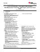
TVP5147M1 SLES140G – JULY 2005 – REVISED FEBRUARY 2012 www.ti.com NTSC/PAL/SECAM 2 11-Bit Digital Video Decoder With Macrovision™ Detection, YPbPr Inputs, and 5-Line Comb Filter Check for Samples: TVP5147M1 1 Introduction 1.1 Features 12345 • Two 30-MSPS 11-bit A/D channels with programmable gain control • Supports NTSC (J, M, 4.
TVP5147M1 www.ti.com SLES140G – JULY 2005 – REVISED FEBRUARY 2012 core, 3.3-V for digital I/O, and 1.8-V/3.
TVP5147M1 SLES140G – JULY 2005 – REVISED FEBRUARY 2012 1.2 www.ti.com Description The TVP5147M1 device is a high-quality, single-chip digital video decoder that digitizes and decodes all popular baseband analog video formats into digital component video. The TVP5147M1 decoder supports the analog-to-digital (A/D) conversion of component YPbPr signals, as well as the A/D conversion and decoding of NTSC, PAL, and SECAM composite and S-video into component YCbCr.
TVP5147M1 www.ti.com 1.3 Applications • • • • • • • • • • 1.4 SLES140G – JULY 2005 – REVISED FEBRUARY 2012 DLP™ projectors Digital TV LCD TV/monitors DVD recorders PVR PC video cards Video capture/video editing Video conferencing Automotive Industrial Related Products TVP5146M2 NTSC/PAL/SECAM 2 11-Bit Digital Video Decoder With Macrovision™ Detection, YPbPr/RGB Inputs, and 5-Line Comb Filter TVP5150AM1 Ultralow Power NTSC/PAL/SECAM Video Decoder With Robust Sync Detector 1.
TVP5147M1 SLES140G – JULY 2005 – REVISED FEBRUARY 2012 1.6 www.ti.
TVP5147M1 www.ti.com 1.
TVP5147M1 SLES140G – JULY 2005 – REVISED FEBRUARY 2012 1.8 www.ti.com Terminal Functions Table 1-1. Terminal Functions TERMINAL NAME NO. I/O DESCRIPTION Analog Video VI_1_A 80 I/O VI_1_B 1 I VI_1_C 2 I VI_2_A 7 I VI_2_B 8 I VI_2_C 9 I VI_3_A 16 I VI_3_B 17 I VI_3_C 18 I VI_4_A 23 I DATACLK 40 O Line-locked data output clock XTAL1 74 I External clock reference input. It can be connected to an external oscillator with a 1.8-V compatible clock signal or a 14.
TVP5147M1 www.ti.com SLES140G – JULY 2005 – REVISED FEBRUARY 2012 Table 1-1. Terminal Functions (continued) TERMINAL NAME NO. CH2_A18VDD 11 CH1_A33GND 3 CH2_A33GND 6 CH1_A33VDD 4 CH2_A33VDD 5 I/O DESCRIPTION Analog 3.3-V return Analog power. Connect to 3.3 V. DGND 27, 32, 42, 56, 68 Digital return DVDD 31, 41, 55, 67 Digital power. Connect to 1.8 V. IOGND 39, 49, 62 Digital power return IOVDD 38, 48, 61 Digital power. Connect to 3.3 V or less for reduced noise.
TVP5147M1 SLES140G – JULY 2005 – REVISED FEBRUARY 2012 www.ti.com 2 Functional Description 2.1 Analog Processing and A/D Converters Figure 2-1 shows a functional diagram of the analog processors and A/D converters, which provide the analog interface to all video inputs. It accepts up to ten inputs and performs source selection, video clamping, video amplification, A/D conversion, and gain and offset adjustments to center the digitized video signal.
TVP5147M1 www.ti.com 2.1.1 SLES140G – JULY 2005 – REVISED FEBRUARY 2012 Video Input Switch Control The TVP5147M1 decoder has two analog channels that accept up to ten video inputs. The user can configure the internal analog video switches via the I2C interface.
TVP5147M1 SLES140G – JULY 2005 – REVISED FEBRUARY 2012 2.1.5 www.ti.com A/D Converters All ADCs have a resolution of 11 bits and can operate up to 30 MSPS. All A/D channels receive an identical clock from the on-chip phase-locked loop (PLL) at a frequency between 24 MHz and 30 MHz. All ADC reference voltages are generated internally. 2.2 Digital Video Processing Figure 2-2 is a block diagram of the TVP5147M1 digital video decoder processing.
TVP5147M1 www.ti.com SLES140G – JULY 2005 – REVISED FEBRUARY 2012 The 10-bit composite video is multiplied by the subcarrier signals in the quadrature demodulator to generate color difference signals U and V. The U and V signals are then sent to low-pass filters to achieve the desired bandwidth. An adaptive 5-line comb filter separates UV from Y based on the unique property of color phase shifts from line to line.
TVP5147M1 SLES140G – JULY 2005 – REVISED FEBRUARY 2012 2.2.2.1 www.ti.com Color Low-Pass Filter 10 10 0 0 −10 −10 −20 −20 Amplitude − dB Amplitude − dB High filter bandwidth preserves sharp color transitions and produces crisp color boundaries. However, for nonstandard video sources that have asymmetrical U and V side bands, it is desirable to limit the filter bandwidth to avoid UV crosstalk. The color low-pass filter bandwidth is programmable to enable one of the three notch filters.
TVP5147M1 www.ti.com 2.2.2.2 SLES140G – JULY 2005 – REVISED FEBRUARY 2012 Y/C Separation Y/C separation can be done using adaptive 5-line (5-H delay) comb filters or a chroma trap filter. The comb filter can be selectively bypassed in the luma or chroma path. If the comb filter is bypassed in the luma path, then chroma trap filters are used which are shown in Figure 2-6 and Figure 2-7. The TI patented adaptive comb filter algorithm reduces artifacts such as hanging dots at color boundaries.
TVP5147M1 SLES140G – JULY 2005 – REVISED FEBRUARY 2012 2.2.3 www.ti.com Luminance Processing The digitized composite video signal passes through either a luminance comb filter or a chroma trap filter, either of which removes chrominance information from the composite signal to generate a luminance signal. The luminance signal is then fed into the input of a peaking circuit. Figure 2-8 illustrates the basic functions of the luminance data path.
TVP5147M1 www.ti.com 2.3 SLES140G – JULY 2005 – REVISED FEBRUARY 2012 Clock Circuits An internal line-locked PLL generates the system and pixel clocks. A 14.318-MHz clock is required to drive the PLL. This can be input to the TVP5147M1 decoder at the 1.8-V level on terminal 74 (XTAL1), or a crystal of 14.318-MHz fundamental resonant frequency can be connected across terminals 74 and 75 (XTAL2).
TVP5147M1 SLES140G – JULY 2005 – REVISED FEBRUARY 2012 www.ti.com Valid Sample Invalid Sample Reserved RTC 128 CLK 18 CLK M S B L S B 22 0 S 45 CLK 23-Bit Fsc PLL Increment R 3 CLK 1 CLK Start Bit NOTE: RTC reset bit (R) is active-low, Sequence bit (S) PAL: 1 = (R-Y) line normal, 0 = (R-Y) line inverted, NTSC: 1 = no change Figure 2-11. RTC Timing 2.5 Output Formatter The output formatter sets how the data is formatted for output on the TVP5147M1 output buses.
TVP5147M1 www.ti.com SLES140G – JULY 2005 – REVISED FEBRUARY 2012 Table 2-2. Summary of Line Frequencies, Data Rates, and Pixel/Line Counts COLOR SUBCARRIER FREQUENCY (MHz) HORIZONTAL LINE RATE (kHz) 13.5 3.579545 15.73426 13.5 4.43361875 15.73426 525 13.5 3.57561149 15.73426 720 525 13.5 4.43361875 15.73426 720 625 13.5 4.43361875 15.625 864 720 625 13.5 4.43361875 15.625 PAL-Nc 864 720 625 13.5 3.58205625 15.625 SECAM 864 720 625 13.5 Dr = 4.406250 Db = 4.
TVP5147M1 SLES140G – JULY 2005 – REVISED FEBRUARY 2012 www.ti.com 525 Line 525 1 2 3 4 5 6 7 8 9 10 11 21 22 First Field Video HS VS VS Start VS Stop CS FID VBLK VBLK Start 262 263 VBLK Stop 264 265 266 267 268 269 270 271 272 283 284 285 Second Field Video HS VS VS Start VS Stop CS FID VBLK VBLK Start VBLK Stop NOTE: Line numbering conforms to ITU-R BT.470. Figure 2-12.
TVP5147M1 www.ti.com SLES140G – JULY 2005 – REVISED FEBRUARY 2012 625 Line 622 623 624 625 1 2 3 4 5 6 7 23 8 24 25 First Field Video HS VS VS Start VS Stop CS FID VBLK VBLK Start 310 311 VBLK Stop 312 313 314 315 316 317 318 319 320 321 336 337 338 Second Field Video HS VS VS Start VS Stop CS FID VBLK VBLK Start VBLK Stop NOTE: Line numbering conforms to ITU-R BT.470. Figure 2-13.
TVP5147M1 SLES140G – JULY 2005 – REVISED FEBRUARY 2012 www.ti.com 0 DATACLK Y[9:0] Cb Y Cr Y EAV EAV EAV EAV 1 3 4 2 Horizontal Blanking HS Start SAV SAV SAV SAV Cb0 1 2 3 4 Y0 Cr0 Y1 HS Stop HS A C B D AVID AVID Stop AVID Start DATACLK = 2 × Pixel Clock Mode A B C D NTSC 601 106 128 42 276 PAL 601 112 128 48 288 NOTE: ITU-R BT.656 10-bit 4:2:2 timing with 2× pixel clock reference Figure 2-14.
TVP5147M1 www.ti.com SLES140G – JULY 2005 – REVISED FEBRUARY 2012 0 DATACLK Y[9:0] Y Y Y Y Horizontal Blanking CbCr[9:0] Cb Cr Cb Cr Horizontal Blanking HS Start Y0 Y1 Y2 Y3 Cb0 Cr0 Cb1 Cr1 HS Stop HS A C B 2 D AVID AVID Stop AVID Start NOTE: AVID rising edge occurs four clock cycles early. DATACLK = 1 × Pixel Clock Mode A B C D NTSC 601 53 64 19 136 PAL 601 56 64 22 142 NOTE: 20-bit 4:2:2 timing with 1× pixel clock reference Figure 2-15.
TVP5147M1 SLES140G – JULY 2005 – REVISED FEBRUARY 2012 www.ti.com HS First Field B/2 B/2 VS HS H/2 + B/2 Second Field H/2 + B/2 VS 10-Bit (PCLK = 2 × Pixel Clock) 20-Bit (PCLK = 1 × Pixel Clock) Mode B/2 H/2 B/2 H/2 NTSC 601 64 858 32 429 PAL 601 64 864 32 432 Figure 2-16. VSYNC Position With Respect to HSYNC 2.5.2 Embedded Syncs Standards with embedded syncs insert the SAV and EAV codes into the data stream on the rising and falling edges of AVID.
TVP5147M1 www.ti.com SLES140G – JULY 2005 – REVISED FEBRUARY 2012 Because SDA and SCL are kept open drain at a logic-high output level or when the bus is not driven, the user must connect SDA and SCL to a positive supply voltage via a pullup resistor on the board. The slave addresses select signal, terminal 37 (I2CA), enables the use of two TVP5147M1 devices tied to the same I2C bus, because it controls the least-significant bit of the I2C device address. Table 2-4.
TVP5147M1 SLES140G – JULY 2005 – REVISED FEBRUARY 2012 2.6.3 www.ti.com VBUS Access The TVP5147M1 decoder has additional internal registers accessible through an indirect access to an internal 24-bit address wide VBUS. Figure 2-17 shows the VBUS register access.
TVP5147M1 www.ti.com 2.7 SLES140G – JULY 2005 – REVISED FEBRUARY 2012 VBI Data Processor The TVP5147M1 VBI data processor (VDP) slices various data services like teletext (WST, NABTS), closed caption (CC), wide screen signaling (WSS), program delivery control (PDC), vertical interval time code (VITC), video program system (VPS), copy generation management system (CGMS) data, and electronic program guide (Gemstar) 1x/2x. Table 2-6 shows the supported VBI system.
TVP5147M1 SLES140G – JULY 2005 – REVISED FEBRUARY 2012 2.7.1 www.ti.com VBI FIFO and Ancillary Data in Video Stream Sliced VBI data can be output as ancillary data in the video stream in ITU-R BT.656 mode. VBI data is output on the Y[9:2] terminals during the horizontal blanking period. Table 2-7 shows the header format and sequence of the ancillary data inserted into the video stream. This format is also used to store any VBI data into the FIFO. The size of the FIFO is 512 bytes.
TVP5147M1 www.ti.com 2.7.2 SLES140G – JULY 2005 – REVISED FEBRUARY 2012 VBI Raw Data Output The TVP5147M1 decoder can output raw A/D video data at twice the sampling rate for external VBI slicing. This is transmitted as an ancillary data block, although somewhat differently from the way the sliced VBI data is transmitted in the FIFO format as described in Section 2.7.1. The samples are transmitted during the active portion of the line. VBI raw data uses ITU-R BT.656 format having only luma data.
TVP5147M1 SLES140G – JULY 2005 – REVISED FEBRUARY 2012 www.ti.com The following register writes must be made before normal operation of the device. STEP I2C SUBADDRESS I2C DATA 1 0x03 0x01 2 0x03 0x00 When using any industrial temperature range device (TVP5147M1IPFP and TVP5147M1IPFPQ1), the following I2C register writes must be executed following device power up and RESETB to properly initialize VBUS register 0xA00014.
TVP5147M1 www.ti.com SLES140G – JULY 2005 – REVISED FEBRUARY 2012 2.10 Internal Control Registers The TVP5147M1 decoder is initialized and controlled by a set of internal registers that define the operating parameters of the entire device. Communication between the external controller and the TVP5147M1 is through a standard I2C host port interface, as described earlier. Table 2-10 shows the summary of these registers.
TVP5147M1 SLES140G – JULY 2005 – REVISED FEBRUARY 2012 www.ti.com Table 2-10.
TVP5147M1 www.ti.com SLES140G – JULY 2005 – REVISED FEBRUARY 2012 Table 2-10.
TVP5147M1 SLES140G – JULY 2005 – REVISED FEBRUARY 2012 www.ti.com Table 2-11.
TVP5147M1 www.ti.com SLES140G – JULY 2005 – REVISED FEBRUARY 2012 2.11 Register Definitions Table 2-12. Input Select Register Subaddress Default 00h 00h 7 6 5 4 3 Input select [7:0] 2 1 0 Ten input terminals can be configured to support composite, S-video, and component YPbPr as listed in Table 2-13. User must follow this table properly for S-video and component applications because only the terminal configurations listed in Table 2-13 are supported. Table 2-13.
TVP5147M1 SLES140G – JULY 2005 – REVISED FEBRUARY 2012 www.ti.com Table 2-14.
TVP5147M1 www.ti.com SLES140G – JULY 2005 – REVISED FEBRUARY 2012 Table 2-16. Operation Mode Control Register Subaddress Default 03h 00h 7 6 Reserved 5 4 H-PLL response time 3 2 Reserved 1 0 Power save H-PLL response time 00 = Adaptive mode (default). 01 = Reserved mode. 10 = Fast mode. 11 = Normal mode. When in the Normal mode, the horizontal PLL (H-PLL) response time is set to its slowest setting.
TVP5147M1 SLES140G – JULY 2005 – REVISED FEBRUARY 2012 www.ti.com Table 2-18. Color Killer Register Subaddress Default 05h 10h 7 Reserved 6 5 Automatic color killer 4 3 2 Color killer threshold [4:0] 1 0 Automatic color killer: 00 = Automatic mode (default) 01 = Reserved 10 = Color killer enabled, the UV terminals are forced to a zero color state 11 = Color killer disabled Color killer threshold [4:0]: 11111 = 31 (maximum) 10000 = 16 (default) 00000 = 0 (minimum) Table 2-19.
TVP5147M1 www.ti.com SLES140G – JULY 2005 – REVISED FEBRUARY 2012 Table 2-20.
TVP5147M1 SLES140G – JULY 2005 – REVISED FEBRUARY 2012 www.ti.com Table 2-23. Luminance Contrast Register Subaddress Default 0Ah 80h 7 6 5 4 3 2 1 0 Contrast [7:0] Contrast [7:0]: This register works for CVBS and S-Video luminance. See subaddress 2Fh.
TVP5147M1 www.ti.com SLES140G – JULY 2005 – REVISED FEBRUARY 2012 Table 2-26. Chrominance Processing Control 1 Register Subaddress Default 7 0Dh 00h 6 Reserved 5 4 Color PLL reset 3 Chroma adaptive comb enable 2 Reserved 1 0 Automatic color gain control [1:0] Color PLL reset: 0 = Color subcarrier PLL not reset (default) 1 = Color subcarrier PLL reset Chrominance adaptive comb enable: This bit is effective on composite video only.
TVP5147M1 SLES140G – JULY 2005 – REVISED FEBRUARY 2012 www.ti.com Table 2-29. G/Y Gain (Contrast) Register Subaddress Default 11h 80h 7 6 5 4 3 2 1 0 G/Y gain [7:0] G/Y component gain (contrast): 0000 0000 = minimum 1000 0000 = default 1111 1111 = maximum For component video outputs, the total luma gain relative to the nominal luma gain as a function of the G/Y gain[7:0] is as follows: Luma gain = (nominal_luminance_gain) × (G/Y gain [7:0] / 128) Table 2-30.
TVP5147M1 www.ti.com SLES140G – JULY 2005 – REVISED FEBRUARY 2012 Table 2-32. AVID Start Pixel Register Subaddress Default Subaddress 16h 17h 16h–17h 55h 7 6 5 Reserved 4 3 AVID start [7:0] AVID active 2 Reserved 1 0 AVID start [9:8] AVID active: 0 = AVID out active in VBLK (default) 1 = AVID out inactive in VBLK AVID start [9:0]: AVID start pixel number, this is an absolute pixel location from HSYNC start pixel 0.
TVP5147M1 SLES140G – JULY 2005 – REVISED FEBRUARY 2012 www.ti.com Table 2-35. HSYNC Stop Pixel Register Subaddress Default Subaddress 1Ch 1Dh 1Ch–1Dh 040h 7 6 5 4 3 HSYNC stop [7:0] 2 Reserved 1 0 HSYNC stop [9:8] HSYNC stop [9:0]: This is an absolute pixel location from HSYNC start pixel 0. The TVP5147M1 decoder updates the HSYNC stop only when the HSYNC stop MSB is written to.
TVP5147M1 www.ti.com SLES140G – JULY 2005 – REVISED FEBRUARY 2012 Table 2-39. VBLK Stop Line Register Subaddress Default 24h–25h 015h Subaddress 24h 25h 7 6 5 4 3 VBLK stop [7:0] 2 1 Reserved 0 VBLK stop [9:8] VBLK stop [9:0]: This is an absolute line number. The TVP5147M1 decoder updates the VBLK stop only when the VBLK stop MSB is written to. If the user changes these registers, then the TVP5147M1 decoder retains values in different modes until this device resets (see Table 2-32).
TVP5147M1 SLES140G – JULY 2005 – REVISED FEBRUARY 2012 www.ti.com Table 2-42. CTI Delay Register Subaddress Default 2Dh 00h 7 6 5 Reserved 4 3 2 1 CTI delay [2:0] 0 1 0 CTI delay [2:0]: Sets the delay of the Y channel with respect to Cb/Cr in the CTI block 011 = 3-pixel delay 001 = 1-pixel delay 000 = 0 delay (default) 111 = −1-pixel delay 100 = −4-pixel delay Table 2-43.
TVP5147M1 www.ti.com SLES140G – JULY 2005 – REVISED FEBRUARY 2012 Table 2-45.
TVP5147M1 SLES140G – JULY 2005 – REVISED FEBRUARY 2012 www.ti.com Table 2-47.
TVP5147M1 www.ti.com SLES140G – JULY 2005 – REVISED FEBRUARY 2012 Table 2-49.
TVP5147M1 SLES140G – JULY 2005 – REVISED FEBRUARY 2012 www.ti.com Table 2-50.
TVP5147M1 www.ti.com SLES140G – JULY 2005 – REVISED FEBRUARY 2012 Table 2-51.
TVP5147M1 SLES140G – JULY 2005 – REVISED FEBRUARY 2012 www.ti.com Table 2-53.
TVP5147M1 www.ti.com SLES140G – JULY 2005 – REVISED FEBRUARY 2012 Table 2-54.
TVP5147M1 SLES140G – JULY 2005 – REVISED FEBRUARY 2012 www.ti.com Table 2-56. Video Standard Status Register Subaddress 7 Autoswitch 3Fh Read only 6 5 4 3 2 Reserved 1 Video standard [2:0] 0 Autoswitch mode 0 = Single standard set 1 = Autoswitch mode enabled Video standard [2:0]: CVBS and S-Video Reserved (M, J) NTSC (B, D, G, H, I, N) PAL (M) PAL (Combination-N) PAL NTSC 4.
TVP5147M1 www.ti.com SLES140G – JULY 2005 – REVISED FEBRUARY 2012 Table 2-58.
TVP5147M1 SLES140G – JULY 2005 – REVISED FEBRUARY 2012 www.ti.com Table 2-60. AFE Coarse Gain for CH 2 Register Subaddress Default 47h 20h 7 6 5 4 3 2 CGAIN 2 [3:0] 1 0 1 0 Reserved CGAIN 2 [3:0]: Coarse Gain = 0.5 + (CGAIN 2)/10 where 0 ≤ CGAIN 2 ≤ 15. This register works only in manual gain control mode. When AGC is active, writing to any value is ignored. 1111 = 2 1110 = 1.9 1101 = 1.8 1100 = 1.7 1011 = 1.6 1010 = 1.5 1001 = 1.4 1000 = 1.3 0111 = 1.2 0110 = 1.1 0101 = 1 0100 = 0.
TVP5147M1 www.ti.com SLES140G – JULY 2005 – REVISED FEBRUARY 2012 Table 2-62. AFE Coarse Gain for CH 4 Register Subaddress Default 49h 20h 7 6 5 4 3 2 CGAIN 4 [3:0] 1 0 Reserved CGAIN 4 [3:0]: Coarse Gain = 0.5 + (CGAIN 4)/10 where 0 ≤ CGAIN 4 ≤ 15. This register works only in manual gain control mode. When AGC is active, writing to any value is ignored. 1111 = 2 1110 = 1.9 1101 = 1.8 1100 = 1.7 1011 = 1.6 1010 = 1.5 1001 = 1.4 1000 = 1.3 0111 = 1.2 0110 = 1.1 0101 = 1 0100 = 0.9 0011 = 0.
TVP5147M1 SLES140G – JULY 2005 – REVISED FEBRUARY 2012 www.ti.com Table 2-64. AFE Fine Gain for Y_Chroma Register Subaddress Default Subaddress 4Ch 4Dh 4Ch–4Dh 900h 7 6 5 4 3 2 1 0 FGAIN 2 [7:0] Reserved FGAIN 2 [11:8] FGAIN 2 [11:0]: This gain applies to component Y channel or S-video chroma (see AFE fine gain for Pb register, Table 2-63). This register works only in manual gain control mode. When AGC is active, writing to any value is ignored. 1111 1111 1111 = 1.9995 1100 0000 0000 = 1.
TVP5147M1 www.ti.com SLES140G – JULY 2005 – REVISED FEBRUARY 2012 Table 2-67. Field ID Control Register Subaddress Default 7 57h 00h 6 5 4 3 Reserved 2 1 656 version 0 FID control 656 version: 0 = ITU-R BT.656-4 (default) 1 = ITU-R BT.
TVP5147M1 SLES140G – JULY 2005 – REVISED FEBRUARY 2012 www.ti.com Table 2-68.
TVP5147M1 www.ti.com SLES140G – JULY 2005 – REVISED FEBRUARY 2012 Table 2-69. Back-End AGC Control Register Subaddress Default 6Ch 08h 7 6 5 4 Reserved 3 1 2 Peak 1 Color 0 Sync This register disables the back-end AGC when the front-end AGC uses specific amplitude references (sync-height, color burst, or composite peak) to decrement the front-end gain.
TVP5147M1 SLES140G – JULY 2005 – REVISED FEBRUARY 2012 www.ti.com Table 2-73.
TVP5147M1 www.ti.com SLES140G – JULY 2005 – REVISED FEBRUARY 2012 Table 2-74. F-Bit and V-Bit Control 2 Register Subaddress Default 75h 12h 7 Rabbit 6 5 4 Fast lock Reserved 3 2 F and V [1:0] 1 Phase detector 0 HPLL Rabbit: Enable rabbit ear 0 = Disabled (default) 1 = Enabled Fast lock: Enable fast lock where vertical PLL is reset and a 2-second timer is initialized when vertical lock is lost; during time-out the detected input VSYNC is output.
TVP5147M1 SLES140G – JULY 2005 – REVISED FEBRUARY 2012 www.ti.com Table 2-76. Horizontal Shake Increment Register Subaddress Default 77h 64h 7 6 5 4 3 Horizontal shake increment [7:0] 2 1 0 1 AGC increment speed [2:0] 0 Horizontal shake increment [7:0]: 000 0000 =0 000 1010 = 64h (default) 111 1111 = FFh Table 2-77. AGC Increment Speed Register Subaddress Default 78h 06h 7 6 5 Reserved 4 3 2 AGC increment speed [2:0]: Adjusts gain increment speed.
TVP5147M1 www.ti.com SLES140G – JULY 2005 – REVISED FEBRUARY 2012 Table 2-80. Chip ID MSB Register Subaddress 80h Read only 7 6 5 4 3 CHIP ID MSB[7:0] 2 1 0 1 0 1 0 1 0 1 0 Capture CHIP ID MSB[7:0]: This register identifies the MSB of the device ID. Value = 51h Table 2-81. Chip ID LSB Register Subaddress 81h Read only 7 6 5 4 3 CHIP ID LSB [7:0] 2 CHIP ID LSB [7:0]: This register identifies the LSB of the device ID. Value = 47h Table 2-82.
TVP5147M1 SLES140G – JULY 2005 – REVISED FEBRUARY 2012 www.ti.com Table 2-85. Vertical Line Count Register Subaddress 9Ah–9Bh Read only Subaddress 9Ah 9Bh 7 6 5 4 3 Vertical line [7:0] 2 1 Reserved 0 Vertical line [9:8] Vertical line [9:0]: Represent the detected a total number of lines from the previous frame. This can be used with nonstandard video signals such as a VCR in trick mode to synchronize downstream video circuitry.
TVP5147M1 www.ti.com SLES140G – JULY 2005 – REVISED FEBRUARY 2012 Table 2-87.
TVP5147M1 SLES140G – JULY 2005 – REVISED FEBRUARY 2012 www.ti.com Table 2-88.
TVP5147M1 www.ti.com SLES140G – JULY 2005 – REVISED FEBRUARY 2012 1P1[3] D1[3] 1M1[3] 1P1[2] D1[2] 1M1[2] 1P1[1] D1[1] 1M1[1] 1P1[0] D1[0] 1M1[0] NIBBLE 1 D2[3:0] NIBBLE 2 1P2[3:0] 1M2[3:0] PASS 1 D3[3:0] 1P3[3:0] Filter 1 Enable NIBBLE 3 1M3[3:0] 00 D4[3:0] 01 NIBBLE 4 1P4[3:0] PASS 1M4[3:0] 10 D5[3:0] 1P5[3:0] NIBBLE 5 11 1M5[3:0] 2 Filter Logic FILTER 1 D1..D5 2P1..2P5 PASS 2 FILTER 2 2M1..2M5 Filter 2 Enable Figure 2-19. Teletext Filter Function Table 2-89.
TVP5147M1 SLES140G – JULY 2005 – REVISED FEBRUARY 2012 www.ti.com Table 2-90. VDP FIFO Interrupt Threshold Register Subaddress Default BDh 80h 7 6 5 4 3 2 1 0 1 0 FIFO reset Threshold [7:0] Threshold [7:0]: This register is programmed to trigger an interrupt when the number of words in the FIFO exceeds this value. Note: 1 word equals 2 bytes. Table 2-91.
TVP5147M1 www.ti.com SLES140G – JULY 2005 – REVISED FEBRUARY 2012 Table 2-94.
TVP5147M1 SLES140G – JULY 2005 – REVISED FEBRUARY 2012 www.ti.com Table 2-98. VDP Full Field Enable Register Subaddress Default D9h 00h 7 6 5 4 Reserved 3 2 1 0 Full field enable Full field enable: 0 = Disabled full field mode(default) 1 = Enabled full field mode This register enables the full field mode.
TVP5147M1 www.ti.com SLES140G – JULY 2005 – REVISED FEBRUARY 2012 Table 2-103. VBUS Address Register Subaddress Default Subaddress E8h E9h EAh E8h 00h E9h 00h 7 EAh 00h 6 5 4 3 VBUS address [7:0] VBUS address [15:8] VBUS address [23:16] 2 1 0 VBUS address [23:0]: VBUS is a 24-bit wide internal bus. The user needs to program in these registers the 24-bit address of the internal register to be accessed via host port indirect access mode. Table 2-104.
TVP5147M1 SLES140G – JULY 2005 – REVISED FEBRUARY 2012 www.ti.com Table 2-105.
TVP5147M1 www.ti.com SLES140G – JULY 2005 – REVISED FEBRUARY 2012 Table 2-106. Interrupt Status 0 Register Subaddress 7 FIFO THRS F2h Read only 6 TTX 5 WSS/CGMS 4 VPS/Gemstar 3 VITC 2 CC F2 1 CC F1 0 Line Interrupt Status 0 and Interrupt Status 1 registers represent the interrupt status after applying mask bits. Therefore, the status bits are the result of a logical AND between the raw status and mask bits.
TVP5147M1 SLES140G – JULY 2005 – REVISED FEBRUARY 2012 www.ti.com Table 2-107.
TVP5147M1 www.ti.com SLES140G – JULY 2005 – REVISED FEBRUARY 2012 Table 2-108. Interrupt Mask 0 Register Subaddress 7 FIFO THRS F4h Read only 6 TTX 5 WSS/CGMS 4 VPS/Gemstar 3 VITC 2 CC F2 1 CC F1 0 Line The host Interrupt Mask 0 and Interrupt Mask 1 registers can be used by the external processor to mask unnecessary interrupt sources for the Interrupt Status 0 and Interrupt Status 1 register bits, and for the external interrupt terminal.
TVP5147M1 SLES140G – JULY 2005 – REVISED FEBRUARY 2012 www.ti.com Table 2-109.
TVP5147M1 www.ti.com SLES140G – JULY 2005 – REVISED FEBRUARY 2012 Table 2-110. Interrupt Clear 0 Register Subaddress 7 FIFO THRS F6h Read only 6 TTX 5 WSS/CGMS 4 VPS/Gemstar 3 VITC 2 CC F2 1 CC F1 0 Line The host Interrupt Clear 0 and Interrupt Clear 1 registers are used by the external processor to clear the interrupt status bits in the host Interrupt Status 0 and Interrupt Status 1 registers.
TVP5147M1 SLES140G – JULY 2005 – REVISED FEBRUARY 2012 www.ti.com Table 2-111.
TVP5147M1 www.ti.com SLES140G – JULY 2005 – REVISED FEBRUARY 2012 Table 2-113.
TVP5147M1 SLES140G – JULY 2005 – REVISED FEBRUARY 2012 www.ti.com Table 2-115. VDP V-Chip TV Rating Block 1 Register Subaddress 7 Reserved 80 0540h Read only 6 14-D 5 PG-D 4 Reserved 3 MA-L 2 14-L 1 PG-L 0 Reserved 1 PG-V 0 Y7-FV 1 TV-Y 0 None TV Parental Guidelines Rating Block 3 14-D: When incoming video program is TV-14-D rated, this bit is set high. PG-D: When incoming video program is TV-PG-D rated, this bit is set high.
TVP5147M1 www.ti.com SLES140G – JULY 2005 – REVISED FEBRUARY 2012 Table 2-118. VDP V-Chip MPAA Rating Data Register Subaddress 7 Not Rated 80 0543h Read only 6 X 5 NC-17 4 R 3 PG-13 2 PG 1 G 0 NA MPAA Rating Block (E5h) Not Rated: When incoming video program is Not Rated rated in MPAA Rating, this bit is set high. X: When incoming video program is X rated in MPAA Rating, this bit is set high. NC-17: When incoming video program is NC-17 rated in MPAA Rating, this bit is set high.
TVP5147M1 SLES140G – JULY 2005 – REVISED FEBRUARY 2012 www.ti.com Table 2-119.
TVP5147M1 www.ti.com SLES140G – JULY 2005 – REVISED FEBRUARY 2012 Table 2-120.
TVP5147M1 SLES140G – JULY 2005 – REVISED FEBRUARY 2012 www.ti.com Table 2-121. Analog Output Control 2 Register Subaddress Default A0 005Eh B2h 7 6 Reserved 5 4 Input Select [1:0] 3 2 1 0 Gain[3:0] Analog input select [1:0]: These bits are effective when manual input select bit is set to 1 at subaddress 7Fh, bit 1. 00 = CH1 selected 01 = CH2 selected 10 = CH3 selected 11= CH4 selected (default) Analog output PGA gain [3:0]: These bits are effective when analog output AGC is disabled.
TVP5147M1 www.ti.com SLES140G – JULY 2005 – REVISED FEBRUARY 2012 3 Electrical Specifications 3.1 Absolute Maximum Ratings over operating free-air temperature range (unless otherwise noted) (1) IOVDD to IOGND DVDD to DGND A33VDD (2) to A33GND (3) MIN MAX UNIT 0.5 4 V –0.2 2 V –0.3 3.6 V –0.2 2 V Supply voltage range A18VDD (4) to A18GND (5) VI to DGND Digital input voltage range –0.5 4.5 V VO to DGND Digital output voltage range –0.5 4.
TVP5147M1 SLES140G – JULY 2005 – REVISED FEBRUARY 2012 3.2 www.ti.com Recommended Operating Conditions IOVDD Supply voltage, digital DVDD Supply voltage, digital AVDD33 Supply voltage, analog AVDD18 Supply voltage, analog VI(P-P) Analog input voltage, analog (ac-coupling necessary) Commercial Commercial MAX 3.3 3.6 1.65 1.8 1.95 1.7 1.8 1.9 3 3.3 3.6 1.65 1.8 1.95 1.7 1.8 1.9 0.
TVP5147M1 www.ti.com 3.4 SLES140G – JULY 2005 – REVISED FEBRUARY 2012 Electrical Characteristics For minimum/maximum values: IOVDD = 3 V to 3.6 V, AVDD33 = 3 V to 3.6 V, Commercial: AVDD18 = 1.65 V to 1.95 V, DVDD = 1.65 V to 1.95 V, TA = 0°C to 70°C Industrial: AVDD18 = 1.7 V to 1.9 V, DVDD = 1.7 V to 1.9 V, TA = −40°C to 85°C For typical values: IOVDD = AVDD33 = 3.3 V, AVDD18 = DVDD = 1.8 V, TA = 25°C DC Electrical Characteristics (1) 3.
TVP5147M1 SLES140G – JULY 2005 – REVISED FEBRUARY 2012 3.7 www.ti.com Clocks, Video Data, Sync Timing PARAMETER TEST CONDITIONS MIN TYP MAX 45 50 55 Duty cycle, DATACLK t1 High time, DATACLK 18.5 t2 Low time, DATACLK 18.5 t3 Fall time, DATACLK 90% to 10% t4 Rise time, DATACLK t5 Output delay time UNIT % ns ns 4 ns 10% to 90% 4 ns Commercial 10 Industrial 12 ns t2 t1 VOH DATACLK VOL t4 t3 VOH Y, C, AVID, VS, HS, FID Valid Data Valid Data VOL t5 Figure 3-1.
TVP5147M1 www.ti.com 3.9 SLES140G – JULY 2005 – REVISED FEBRUARY 2012 Thermal Specifications PARAMETER TEST CONDITIONS (1) MIN TYP MAX UNIT θJA Junction-to-ambient thermal resistance, still air Thermal pad soldered to 4-layer High-K PCB 19.04 °C/W θJC Junction-to-case thermal resistance, still air Thermal pad soldered to 4-layer High-K PCB 0.
TVP5147M1 SLES140G – JULY 2005 – REVISED FEBRUARY 2012 4 www.ti.com Example Register Settings The following example register settings are provided only as a reference. These settings (given the assumed input connector, video format, and output format) set the TVP5147M1 decoder and provide video output. Example register settings for other features and the VBI data processor are not provided here. 4.1 4.1.
TVP5147M1 www.ti.com 4.2 4.2.1 SLES140G – JULY 2005 – REVISED FEBRUARY 2012 Example 2 Assumptions Input connector: S-video [VI_2_C (luma), VI_1_C (chroma)] 4.2.2 Video format: NTSC (J, M, 443), PAL (B, D, G, H, I, N, Nc, 60) or SECAM (default) Output format: 10-bit ITU-R BT.
TVP5147M1 SLES140G – JULY 2005 – REVISED FEBRUARY 2012 4.3 4.3.1 www.ti.com Example 3 Assumptions Input connector: Component [VI_1_B (Pb), VI_2_B (Y), VI_3_B (Pr)] 4.3.2 Video format: 480I, 576I Output format: 20-bit ITU-R BT.656 with discrete sync outputs Recommended Settings Recommended I2C writes: This setup requires additional writes to output the discrete sync 20-bit 4:2:2 data, HS, and VS, and to autoswitch between all video formats mentioned above.
TVP5147M1 www.ti.com SLES140G – JULY 2005 – REVISED FEBRUARY 2012 5 Application Information 5.1 Application Example C0 FID VS/VBLK 2.2 kΩ A3.3VDD IOVDD3.3 V C3 C4 C5 XTAL1 XTAL2 A1.8VDD 22 Ω C1 C2 2.2 kΩ HS/CS DVDD1.8 V 12 kΩ 0.1 µF (2) 80 79 78 77 76 75 74 73 72 71 70 69 68 67 66 65 64 VI_1_A 75 Ω 1 kΩ 22 kΩ VI_1A VI_1B VI_1C 1 2 75 Ω (3) 0.1 µF (3) 0.1 µF (2) 0.1 µF (3) VI_2A VI_2B VI_2C 75 Ω (3) 0.1 µF (3) VI_3A VI_3B VI_3C 75 Ω (3) 0.
TVP5147M1 SLES140G – JULY 2005 – REVISED FEBRUARY 2012 5.2 www.ti.com Designing With PowerPAD™ Devices The TVP5147 device is housed in a high-performance, thermally enhanced, 80-terminal PowerPAD package (TI package designator: 80PFP). Use of the PowerPAD package does not require special considerations except to note that the thermal pad, which is an exposed die pad on the bottom of the device, is a metallic thermal and electrical conductor.
TVP5147M1 www.ti.com SLES140G – JULY 2005 – REVISED FEBRUARY 2012 Revision History NOTE: Page numbers for previous revisions may differ from page numbers in the current version. REVISION SLES140 COMMENTS Initial release SLES140A Updated Section 2.8 SLES140B Added industrial temperature orderable and updated relevant specifications in Chapter 3 Updated Section 1.2 SLES140C Updated Section 2.11.16, Section 2.11.
PACKAGE OPTION ADDENDUM www.ti.
PACKAGE OPTION ADDENDUM www.ti.com 31-May-2013 continues to take reasonable steps to provide representative and accurate information but may not have conducted destructive testing or chemical analysis on incoming materials and chemicals. TI and TI suppliers consider certain information to be proprietary, and thus CAS numbers and other limited information may not be available for release.
IMPORTANT NOTICE Texas Instruments Incorporated and its subsidiaries (TI) reserve the right to make corrections, enhancements, improvements and other changes to its semiconductor products and services per JESD46, latest issue, and to discontinue any product or service per JESD48, latest issue. Buyers should obtain the latest relevant information before placing orders and should verify that such information is current and complete.