
- TVP5147M1PFP NTSC/PAL/SECAM 2x10-Bit Digital Video Decoder (Rev. A

Functional Description
11
SLES140A—March 2007 TVP5147M1PFP
2.2 Digital Video Processing
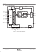
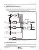
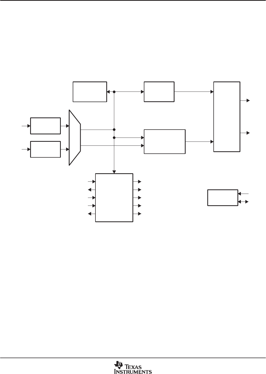
Figure 2−2 is a block diagram of the TVP5147M1 digital video decoder processing. This block receives
digitized video signals from the ADCs and performs composite processing for CVBS and S-video inputs and
YCbCr signal enhancements for CVBS and S-video inputs. It also generates horizontal and vertical syncs and
other output control signals such as genlock for CVBS and S-video inputs. Additionally, it can provide field
identification, horizontal and vertical lock, vertical blanking, and active video window indication signals. The
digital data output can be programmed to two formats: 20-bit 4:2:2 with external syncs or 10-bit 4:2:2 with
embedded/separate syncs. The circuit detects pseudosync pulses, AGC pulses, and color striping in
Macrovision-encoded copy-protected material. Information present in the VBI interval can be retrieved and
either inserted in the ITU-R BT.656 output as ancillary data or stored in internal FIFO and/or registers for
retrieval via the host port interface.
Copy
Protection
Detector
VBI Data
Processor
Output
Formatter
Composite
Processor
CVBS/Y
C/CbCr
YCbCr
Y[9:0]
Timing
Processor
AVID
FID
GLCO
XTAL1
XTAL2
RESETB
CH1 A/D
CH2 A/D
HS/CS
VS/VBLK
DATACLK
C[9:0]
Host
Interface
SCL
SDA
Slice VBI Data
2×
Decimation
PWDN
2×
Decimation
Figure 2−2. Digital Video Processing Block Diagram
2.2.1 2× Decimation Filter
All input signals are typically oversampled by a factor of 2 (27 MHz). The A/D outputs initially pass through
decimation filters that reduce the data rate to 1× the pixel rate. The decimation filter is a half-band filter.
Oversampling and decimation filtering can effectively increase the overall signal-to-noise ratio by 3 dB.
2.2.2 Composite Processor
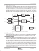
Figure 2−3 is a block diagram of the TVP5147M1 digital composite video processing circuit. This processing
circuit receives a digitized composite or S-video signal from the ADCs and performs Y/C separation (bypassed
for S-video input), chroma demodulation for PAL/NTSC and SECAM, and YUV signal enhancements.
The 10-bit composite video is multiplied by the subcarrier signals in the quadrature demodulator to generate
color difference signals U and V. The U and V signals are then sent to low-pass filters to achieve the desired
bandwidth. An adaptive 5-line comb filter separates UV from Y based on the unique property of color phase
shifts from line to line. The chroma is remodulated through a quadrature modulator and subtracted from
line-delayed composite video to generate luma. This form of Y/C separation is completely complementary,
thus there is no loss of information. However, in some applications, it is desirable to limit the U/V bandwidth
to avoid crosstalk. In that case, notch filters can be turned on. To accommodate some viewing preferences,
a peaking filter is also available in the luma path. Contrast, brightness, sharpness, hue, and saturation controls
are programmable through the host port.