
Datasheet


µA78L00 SERIES
POSITIVE-VOLTAGE REGULATORS
SLVS010S − JANUARY 1976 − REVISED FEBRUARY 2004
6
POST OFFICE BOX 655303 • DALLAS, TEXAS 75265
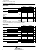
electrical characteristics at specified virtual junction temperature, V
I
= 12 V, I
O
= 40 mA (unless
otherwise noted)
PARAMETER
TEST CONDITIONS
T
†
µA78L06C µA78L06AC
UNIT
PARAMETER TEST CONDITIONS
T
J
†
MIN TYP MAX MIN TYP MAX
UNIT
V 85Vt 20V
I 1At40A
25°C
5.7 6.2 6.7 5.95 6.2 6.45
Output voltage
V
I
= 8.5 V to 20 V, I
O
= 1 mA to 40 mA
0°C to 125°C
5.6 6.8 5.9 6.5
V
Output
voltage
I
O
= 1 mA to 70 mA
0°C to 125°C
5.6 6.8 5.9 6.5
V
Input
V
I
= 8.5 V to 20 V
25°C
35 200 35 175
mV
Input
voltage regulation
V
I
= 9 V to 20 V
25°C
29 150 29 125
mV
Ripple rejection V
I
= 10 V to 20 V, f = 120 Hz 25°C 39 48 40 48 dB
Output
I
O
= 1 mA to 100 mA
25°C
16 80 16 80
mV
Output
voltage regulation
I
O
= 1 mA to 40 mA
25°C
9 40 9 40
mV
Output
noise voltage
f = 10 Hz to 100 kHz 25°C 46 46 µV
Dropout voltage 25°C 1.7 1.7 V
Bias current
25°C
3.9 6 3.9 6
mA
Bias current
125°C
5.5 5.5
mA
Bias
V
I
= 9 V to 20 V
0°C to 125°C
1.5 1.5
mA
Bias
current change
I
O
= 1 mA to 40 mA
0°C to 125°C
0.2 0.1
mA
†
Pulse-testing techniques maintain T
J
as close to T
A
as possible. Thermal effects must be taken into account separately. All characteristics are
measured with a 0.33-µF capacitor across the input and a 0.1-µF capacitor across the output.
electrical characteristics at specified virtual junction temperature, V
I
= 14 V, I
O
= 40 mA (unless
otherwise noted)
PARAMETER
TEST CONDITIONS
T
†
µA78L08C µA78L08AC
UNIT
PARAMETER TEST CONDITIONS
T
J
†
MIN TYP MAX MIN TYP MAX
UNIT
V 105Vt 23V
I 1At40A
25°C
7.36 8 8.64 7.7 8 8.3
Output voltage
V
I
= 10.5 V to 23 V, I
O
= 1 mA to 40 mA
0°C to 125°C
7.2 8.8 7.6 8.4
V
Output
voltage
I
O
= 1 mA to 70 mA
0°C to 125°C
7.2 8.8 7.6 8.4
V
Input volta
g
e
V
I
= 10.5 V to 23 V
25°C
42 200 42 175
mV
Input
voltage
regulation
V
I
= 11 V to 23 V
25°C
36 150 36 125
mV
Ripple rejection V
I
= 13 V to 23 V, f = 120 Hz 25°C 36 46 37 46 dB
Output volta
g
e
I
O
= 1 mA to 100 mA
25°C
18 80 18 80
mV
Output
voltage
regulation
I
O
= 1 mA to 40 mA
25°C
10 40 10 40
mV
Output
noise voltage
f = 10 Hz to 100 kHz 25°C 54 54 µV
Dropout voltage 25°C 1.7 1.7 V
Bias current
25°C
4 6 4 6
mA
Bias current
125°C
5.5 5.5
mA
Bias
V
I
= 11 V to 23 V
0°C to 125°C
1.5 1.5
mA
Bias
current change
I
O
= 1 mA to 40 mA
0°C to 125°C
0.2 0.1
mA
†
Pulse-testing techniques maintain T
J
as close to T
A
as possible. Thermal effects must be taken into account separately. All characteristics are
measured with a 0.33-µF capacitor across the input and a 0.1-µF capacitor across the output.