
Datasheet


μA78L00
SLVS010U –JANUARY 1976–REVISED MAY 2011
www.ti.com
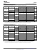
uA78L09 Electrical Characteristics
at specified virtual junction temperature, V
I
= 16 V, I
O
= 40 mA (unless otherwise noted)
μA78L09C μA78L09AC
PARAMETER TEST CONDITIONS T
J
(1)
UNIT
MIN TYP MAX MIN TYP MAX
25°C 8.3 9 9.7 8.6 9 9.4
V
I
= 12 V to 24 V,
I
O
= 1 mA to 40 mA
Output voltage 0°C to 125°C 8.1 9.9 8.55 9.45 V
I
O
= 1 mA to 70 mA 0°C to 125°C 8.1 9.9 8.55 9.45
V
I
= 12 V to 24 V 45 225 45 175
Input voltage
25°C mV
regulation
V
I
= 13 V to 24 V 40 175 40 125
V
I
= 15 V to 25 V,
Ripple rejection 25°C 36 45 38 45 dB
f = 120 Hz
I
O
= 1 mA to 100 mA 19 90 19 90
Output voltage
25°C mV
regulation
I
O
= 1 mA to 40 mA 11 40 11 40
Output noise
f = 10 Hz to 100 kHz 25°C 58 58 μV
voltage
Dropout voltage 25°C 1.7 1.7 V
25°C 4.1 6 4.1 6
Bias current mA
125°C 5.5 5.5
V
I
= 13 V to 24 V 1.5 1.5
Bias current
0°C to 125°C mA
change
I
O
= 1 mA to 40 mA 0.2 0.1
(1) Pulse-testing techniques maintain T
J
as close to T
A
as possible. Thermal effects must be taken into account separately. All
characteristics are measured with a 0.33-μF capacitor across the input and a 0.1-μF capacitor across the output.
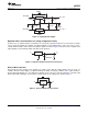
uA78L10 Electrical Characteristics
at specified virtual junction temperature, V
I
= 14 V, I
O
= 40 mA (unless otherwise noted)
μA78L10AC
PARAMETER TEST CONDITIONS T
J
(1)
UNIT
MIN TYP MAX
25°C 9.6 10 10.4
V
I
= 13 V to 25 V, I
O
= 1 mA to 40 mA
Output voltage 0°C to 125°C 9.5 10.5 V
I
O
= 1 mA to 70 mA 0°C to 125°C 9.5 10.5
V
I
= 13 V to 25 V 51 175
Input voltage regulation 25°C mV
V
I
= 14 V to 25 V 42 125
Ripple rejection V
I
= 15 V to 25 V, f = 120 Hz 25°C 37 44 dB
I
O
= 1 mA to 100 mA 20 90
Output voltage regulation 25°C mV
I
O
= 1 mA to 40 mA 11 40
Output noise voltage f = 10 Hz to 100 kHz 25°C 62 μV
Dropout voltage 25°C 1.7 V
25°C 4.2 6
Bias current mA
125°C 5.5
V
I
= 14 V to 25 V 1.5
Bias current change 0°C to 125°C mA
I
O
= 1 mA to 40 mA 0.1
(1) Pulse-testing techniques maintain T
J
as close to T
A
as possible. Thermal effects must be taken into account separately. All
characteristics are measured with a 0.33-μF capacitor across the input and a 0.1-μF capacitor across the output.
6 Submit Documentation Feedback Copyright © 1976–2011, Texas Instruments Incorporated
Product Folder Links :μA78L00