
Datasheet


The UC1637 is a pulse width modulator circuit intended to be used for a variety of
PWM motor drive and amplifier applications requiring either uni-directional or bi-
directional drive circuits. When used to replace conventional drivers, this circuit
can increase efficiency and reduce component costs for many applications. All
necessary circuitry is included to generate an analog error signal and modulate
two bi-directional pulse train outputs in proportion to the error signal magnitude
and polarity.
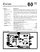
This monolithic device contains a sawtooth oscillator, error amplifier, and two
PWM comparators with
±
100mA output stages as standard features. Protection
circuitry includes under-voltage lockout, pulse-by-pulse current limiting, and a
shutdown port with a 2.5V temperature compensated threshold.
The UC1637 is characterized for operation over the full military temperature range
of -55°C to +125°C, while the UC2637 and UC3637 are characterized for -25°C to
+85°C and 0°C to +70°C, respectively.
Switched Mode Controller for DC Motor Drive
UC1637
UC2637
UC3637
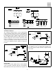
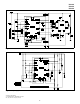
BLOCK DIAGRAM
• Single or Dual Supply
Operation
•
±
2.5V to
±
20V Input Supply
Range
•
±
5% Initial Oscillator
Accuracy;
±
10% Over
Temperature
• Pulse-by-Pulse Current
Limiting
• Under-Voltage Lockout
• Shutdown Input with
Temperature Compensated
2.5V Threshold
• Uncommitted PWM
Comparators for Design
Flexibility
• Dual 100mA, Source/Sink
Output Drivers
Supply Voltage (
±
Vs) . . . . . . . . . . . . . . . . . . . . . . . . . . . . . . . . . . . . . . . . . . . . . . . . . . .
±
20V
Output Current, Source/Sink (Pins 4, 7) . . . . . . . . . . . . . . . . . . . . . . . . . . . . . . . . . . . 500mA
Analog Inputs (Pins 1, 2, 3, 8, 9, 10, 11 12, 13, 14, 15, 16) . . . . . . . . . . . . . . . . . . . . . . .
±
Vs
Error Amplifier Output Current (Pin 17) . . . . . . . . . . . . . . . . . . . . . . . . . . . . . . . . . . .
±
20mA
Oscillator Charging Current (Pin 18). . . . . . . . . . . . . . . . . . . . . . . . . . . . . . . . . . . . . . . -2mA
Power Dissipation at T
A
= 25°C (Note 2) . . . . . . . . . . . . . . . . . . . . . . . . . . . . . . . . 1000mW
Power Dissipation at T
C
= 25°C (Note 2) . . . . . . . . . . . . . . . . . . . . . . . . . . . . . . . . 2000mW
Storage Temperature Range . . . . . . . . . . . . . . . . . . . . . . . . . . . . . . . . . . . -65°C to +150°C
Lead Temperature (Soldering, 10 Seconds). . . . . . . . . . . . . . . . . . . . . . . . . . . . . . . . +300°C
Note 1: Currents are positive into, negative out of the specified terminal.
Note 2: Consult Packaging Section of Databook for thermal limitations and considerations
of package.
FEATURES
ABSOLUTE MAXIMUM RATINGS (Note 1)
DESCRIPTION
6/97