
Datasheet


UC1841
UC2841
UC3841
Programmable, Off-Line, PWM Controller
• All Control, Driving, Monitoring, and
Protection Functions Included
• Low-current, Off-line Start Circuit
• Voltage Feed Forward or Current
Mode Control
• Guaranteed Duty Cycle Clamp
• PWM Latch for Single Pulse per Period
• Pulse-by-Pulse Current Limiting Plus
Shutdown for Over-Current Fault
• No Start-up or Shutdown Transients
• Slow Turn-on Both Initially and After
Fault Shutdown
• Shutdown Upon Over- or
Under-Voltage Sensing
• Latch Off or Continuous Retry After
Fault
• PWM Output Switch Usable to 1A
Peak Current
• 1% Reference Accuracy
• 500kHz Operation
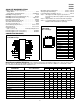
• 18 Pin DIL Package
The UC1841 family of PWM controllers has been designed to increase
the level of versatility while retaining all of the performance features of
the earlier UC1840 devices. While still optimized for highly-efficient boot-
strapped primary-side operation in forward or flyback power converters,
the UC1841 is equally adept in implementing both low and high voltage
input DC to DC converters. Important performance features include a
low-current starting circuit, linear feed-forward for constant volt-second
operation, and compatibility with either voltage or current mode topologies.
In addition to start-up and normal regulating PWM functions, these de-
vices include built in protection from over-voltage, under-voltage, and
over-current fault conditions with the option for either latch-off or automat-
ic restart.
While pin compatible with the UC1840 in all respects except that the po-
larity of the External Stop has been reversed, the UC1841 offers the fol-
lowing improvements:
1. Fault latch reset is accomplished with slow start discharge rather
than recycling the input voltage to the chip.
2. The External Stop input can be used for a fault delay to resist
shutdown from short duration transients.
3. The duty-cycle clamping function has been characterized and
specified.
The UC1841 is characterized for -55°C to +125°C operation while the
UC2841 and UC3841 are designed for -25°C to +85°C and 0°to +70°C,
respectively.
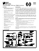
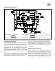
BLOCK DIAGRAM
Note: Positive true logic, latch outputs high with set, reset has priority.
6/93
DESCRIPTIONFEATURES