
Datasheet

UC2950
Half-Bridge Bipolar Switch
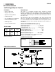
CONNECTION DIAGRAM
SIMPLIFIED SCHEMATIC
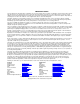
TRUTH TABLE
Source
Drive
Pin 2
Sink Drive
Pin 5
Output
Pin 4
Low
Low
High
High
Low
High
Low
High
Low
Off
High
High
Note: With no load, output voltage will be
HIGH in the OFF state.
ABSOLUTE MAXIMUM RATINGS (Note 1)
Supply Voltage Range, V
C
. . . . . . . . . . . . . . . . . . . . . 8V to 35V
Output Voltage Range, V
O
. . . . . . . . . . . . . . . . –3.0V to V
C
+3V
Input Voltage Range, V
IN
. . . . . . . . . . . . . . . . . . –0.3V to +7.0V
Peak Output Current (100 ms, 10% DC) . . . . . . . . . . . . .
±
4.0A
Continuous Output Current . . . . . . . . . . . . . . . . . . . . . . .
±
2.0A
Power Dissipation with Heat Sink. . . . . . . . . . . . . . . . . . . . 15W
Power Dissipation in Free Air . . . . . . . . . . . . . . . . . . . . . . . . 2W
Operating Temperature Range, T
A
. . . . . . . . . –20°C to +100°C
Storage Temperature Range, T
S
. . . . . . . . . . –55°C to +125°C
Note 1: Consult Packaging section of databook for thermal
limitations and considerations of package.
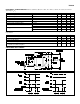
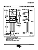
5-PIN TO-220 (TOP VIEW)
T Package
FEATURES
•
Source or Sink 4.0A
•
Supply Voltage to 35V
•
High-Current Output Diodes
•
Tri-State Operation
•
TTL and CMOS Input Compatibility
•
Thermal Shutdown Protection
•
300kHz Operation
•
Low-Cost TO-220 Package
DESCRIPTION
This device is a monolithic integrated circuit designed to provide
high-current switching with low saturation voltages when activated by
low-level logic signals. Source and sink switches may be independently acti
-
vated without regard to timing as a built-in interlock will keep the sink off if
the source is on.
This driver has the high current capability to drive large capacitive loads
with fast rise and fall times; but with high-speed internal flyback diodes, it is
also ideal for inductive loads. Two UC2950s can be used together to form a
full bridge, bipolar motor driver compatible with high frequency chopper cur
-
rent control.
SLUS280A - MAY 1993 - REVISED JULY 2003