PACKAGE OPTION ADDENDUM www.ti.
PACKAGE OPTION ADDENDUM www.ti.
PACKAGE OPTION ADDENDUM www.ti.
PACKAGE OPTION ADDENDUM www.ti.
PACKAGE OPTION ADDENDUM www.ti.
PACKAGE OPTION ADDENDUM www.ti.
PACKAGE OPTION ADDENDUM www.ti.
PACKAGE OPTION ADDENDUM www.ti.
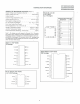
PACKAGE OPTION ADDENDUM www.ti.com 10-Jun-2014 (5) Multiple Device Markings will be inside parentheses. Only one Device Marking contained in parentheses and separated by a "~" will appear on a device. If a line is indented then it is a continuation of the previous line and the two combined represent the entire Device Marking for that device. (6) Lead/Ball Finish - Orderable Devices may have multiple material finish options. Finish options are separated by a vertical ruled line.
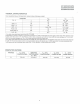
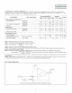
PACKAGE MATERIALS INFORMATION www.ti.com 9-Apr-2014 TAPE AND REEL INFORMATION *All dimensions are nominal Device Package Package Pins Type Drawing UC2842AD8TR SOIC SPQ Reel Reel A0 Diameter Width (mm) (mm) W1 (mm) D 8 2500 330.0 12.4 6.4 B0 (mm) K0 (mm) P1 (mm) W Pin1 (mm) Quadrant 5.2 2.1 8.0 12.0 Q1 UC2842ADTR SOIC D 14 2500 330.0 16.4 6.5 9.0 2.1 8.0 16.0 Q1 UC2842ADWTR SOIC DW 16 2000 330.0 16.4 10.75 10.7 2.7 12.0 16.
PACKAGE MATERIALS INFORMATION www.ti.com 9-Apr-2014 *All dimensions are nominal Device Package Type Package Drawing Pins SPQ Length (mm) Width (mm) Height (mm) UC2842AD8TR SOIC D 8 2500 340.5 338.1 20.6 UC2842ADTR SOIC D 14 2500 333.2 345.9 28.6 UC2842ADWTR SOIC DW 16 2000 367.0 367.0 38.0 UC2843AD8TR SOIC D 8 2500 340.5 338.1 20.6 UC2843ADTR SOIC D 14 2500 333.2 345.9 28.6 UC2844AD8TR SOIC D 8 2500 340.5 338.1 20.
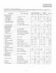
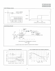
MECHANICAL DATA MCER001A – JANUARY 1995 – REVISED JANUARY 1997 JG (R-GDIP-T8) CERAMIC DUAL-IN-LINE 0.400 (10,16) 0.355 (9,00) 8 5 0.280 (7,11) 0.245 (6,22) 1 0.063 (1,60) 0.015 (0,38) 4 0.065 (1,65) 0.045 (1,14) 0.310 (7,87) 0.290 (7,37) 0.020 (0,51) MIN 0.200 (5,08) MAX Seating Plane 0.130 (3,30) MIN 0.023 (0,58) 0.015 (0,38) 0°–15° 0.100 (2,54) 0.014 (0,36) 0.008 (0,20) 4040107/C 08/96 NOTES: A. B. C. D. E. All linear dimensions are in inches (millimeters).
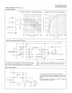
MECHANICAL DATA MPLC004A – OCTOBER 1994 FN (S-PQCC-J**) PLASTIC J-LEADED CHIP CARRIER 20 PIN SHOWN Seating Plane 0.004 (0,10) 0.180 (4,57) MAX 0.120 (3,05) 0.090 (2,29) D D1 0.020 (0,51) MIN 3 1 19 0.032 (0,81) 0.026 (0,66) 4 E 18 D2 / E2 E1 D2 / E2 8 14 0.021 (0,53) 0.013 (0,33) 0.007 (0,18) M 0.050 (1,27) 9 13 0.008 (0,20) NOM D/E D2 / E2 D1 / E1 NO. OF PINS ** MIN MAX MIN MAX MIN MAX 20 0.385 (9,78) 0.395 (10,03) 0.350 (8,89) 0.356 (9,04) 0.141 (3,58) 0.169 (4,29) 28 0.
IMPORTANT NOTICE Texas Instruments Incorporated and its subsidiaries (TI) reserve the right to make corrections, enhancements, improvements and other changes to its semiconductor products and services per JESD46, latest issue, and to discontinue any product or service per JESD48, latest issue. Buyers should obtain the latest relevant information before placing orders and should verify that such information is current and complete.