UCC28019 www.ti.
UCC28019 www.ti.com SLUS755B – APRIL 2007 – REVISED DECEMBER 2007 ORDERING INFORMATION (1) OPERATING TEMPERATURE RANGE, TA PART NUMBER PACKAGE (1) UCC28019D SOIC 8-Pin (D) ead (Pb)-Free/Green UCC28019P Plastic DIP 8 Pin (P) Lead (Pb)-Free/Green –40°C to 125°C SOIC (D) package is available taped and reeled by adding "R" suffix the the above part number, reeled quantities are 2500 devices per reel.
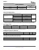
UCC28019 www.ti.com SLUS755B – APRIL 2007 – REVISED DECEMBER 2007 ELECTRICAL CHARACTERISTICS Unless otherwise noted, VCC = 15 VDC, 0.1 µF from VCC to GND, -40°C ≤ TJ = TA ≤ 125°C. All voltages are with respect to GND. Currents are positive into and negative out of the specified terminal. PARAMETER TEST CONDITIONS MIN TYP MAX UNIT VCC Bias Supply IVCC(start) Pre-start current VCC = VCCON – 0.1 V 25 100 200 IVCC(stby) Standby current VSENSE = 0.5 V 1.0 2.1 2.
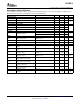
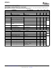
UCC28019 www.ti.com SLUS755B – APRIL 2007 – REVISED DECEMBER 2007 ELECTRICAL CHARACTERISTICS (continued) Unless otherwise noted, VCC = 15 VDC, 0.1 µF from VCC to GND, -40°C ≤ TJ = TA ≤ 125°C. All voltages are with respect to GND. Currents are positive into and negative out of the specified terminal. PARAMETER TEST CONDITIONS MIN TYP MAX UNIT Current Loop gmi Transconductance gain TA = 25°C 0.75 Output linear range 0.95 1.15 ICOMP voltage during OLP VSENSE = 0.
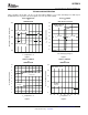
UCC28019 www.ti.com SLUS755B – APRIL 2007 – REVISED DECEMBER 2007 TYPICAL CHARACTERISTICS Unless otherwise noted, VCC = 15 VDC, 0.1 µF from VCC to GND, TJ = TA = 25°C. All voltages are with respect to GND. Currents are positive into and negative out of the specified terminal. SUPPLY CURRENT vs BIAS SUPPLY VOLTAGE UVLO THRESHOLDS vs TEMPERATURE 4.0 12.0 VSENSE = VINS = 3V No Gate Load 11.0 VCC Turn ON (VCCON) 3.0 IVCC - Supply Current - mA VCCON/VCCOFF - UVLO Threshold - V 3.5 10.0 2.5 2.
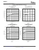
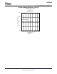
UCC28019 www.ti.com SLUS755B – APRIL 2007 – REVISED DECEMBER 2007 TYPICAL CHARACTERISTICS (continued) OSCILLATOR FREQUENCY vs BIAS SUPPLY VOLTAGE 75 75 73 73 71 71 fSW - Switching Frequency - kHz fSW - Switching Frequency - kHz OSCILLATOR FREQUENCY vs TEMPERATURE 69 Switching Frequency 67 65 63 61 59 69 67 65 63 61 59 57 57 55 55 -60 -35 -10 15 40 65 90 115 Switching Frequency 140 12 10 TJ - Temperature - °C 14 Figure 5. 50 1.8 48 1.6 46 1.
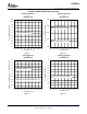
UCC28019 www.ti.com SLUS755B – APRIL 2007 – REVISED DECEMBER 2007 TYPICAL CHARACTERISTICS (continued) VSENSE THRESHOLD vs TEMPERATURE VSENSE THRESHOLD vs TEMPERATURE 5.50 2.0 VOVP / VUVD- VSENSE Threshold - V VOLP – VSENSE Threshold - V 1.8 1.6 1.4 1.2 1.0 Open Loop Protection (VOLP) 0.8 0.6 0.4 5.25 Over-Voltage Protection (VOVP) 5.00 4.75 Under-Voltage Protection (VUVD) 0.2 4.50 0 -60 -35 -10 15 40 65 90 TJ - Temperature - °C 115 -60 140 -35 -10 Figure 9. 1.8 -0.1 1.6 -0.
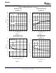
UCC28019 www.ti.com SLUS755B – APRIL 2007 – REVISED DECEMBER 2007 TYPICAL CHARACTERISTICS (continued) MINIMUM OFF TIME vs TEMPERATURE GATE DRIVE SWITCHING vs TEMPERATURE 600 50 VSENSE = 3 V ICOMP = 1 V 500 40 450 35 400 30 350 300 tOFF(min) 25 15 200 10 105 5 100 0 -35 -10 15 40 65 90 115 Fall Time 20 250 -60 CGATE = 4.7 nF VGATE = 2 V - 8 V 45 t - Time - ns t - Time - ns 550 Rise Time -60 140 -35 -10 TJ - Temperature - °C 15 Figure 13.
UCC28019 www.ti.com SLUS755B – APRIL 2007 – REVISED DECEMBER 2007 TYPICAL CHARACTERISTICS (continued) REFERENCE VOLTAGE vs TEMPERATURE 5.50 VREF - Reference Voltage - V VCC = 15V 5.25 Reference Voltage 5.00 4.75 4.50 -60 -35 -10 15 40 65 90 TJ - Temperature - °C 115 140 Figure 17.
UCC28019 www.ti.com SLUS755B – APRIL 2007 – REVISED DECEMBER 2007 DEVICE INFORMATION Connection Diagram UCC28019 Top View (SOIC-8, PDIP-8) GATE 8 2 ICOMP VCC 7 3 ISENSE VSENSE 6 VINS VCOMP 5 1 GND 4 Pin Descriptions Terminal Functions TERMINAL NAME # GATE 8 GND 1 ICOMP 2 I/O O FUNCTION Gate drive: Integrated push-pull gate driver for one or more external power MOSFETs. 2.0-A sink and 1.5-A source capability. Output voltage is clamped at 12.5 V. Ground: Device ground reference.
UCC28019 www.ti.
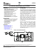
UCC28019 www.ti.com SLUS755B – APRIL 2007 – REVISED DECEMBER 2007 APPLICATION INFORMATION UCC28019 Operation The UCC28019 is a switch-mode controller used in boost converters for power factor correction operating at a fixed frequency in continuous conduction mode. The UCC28019 requires few external components to operate as an active PFC pre-regulator.
UCC28019 www.ti.com SLUS755B – APRIL 2007 – REVISED DECEMBER 2007 Power Supply The UCC28019 operates from an external bias supply. It is recommended that the device be powered from a regulated auxiliary supply. This device is not intended to be used from a bootstrap bias supply. A bootstrap bias supply is fed from the input high voltage through a resistor with sufficient capacitance on VCC to hold up the voltage on VCC until current can be supplied from a bias winding on the boost inductor.
UCC28019 www.ti.com SLUS755B – APRIL 2007 – REVISED DECEMBER 2007 Soft Start VCOMP, the output of the voltage loop transconductance amplifier, is pulled low during UVLO, IBOP, and OLP(Open-Loop Protection)/STANDBY. After the fault condition is released, soft start controls the rate of rise of VCOMP in order to obtain a linear control of the increasing duty cycle as a function of time.
UCC28019 www.ti.com SLUS755B – APRIL 2007 – REVISED DECEMBER 2007 VCC Under-Voltage Lockout (UVLO) During startup, UVLO keeps the device in the off state until VCC rises above the 10.5-V enable threshold, VCCON. With a typical 1 V of hysteresis on UVLO to eliminate noise, the device turns off when VCC drops to the 9.5-V disable threshold, VCCOFF. VCC Auxilary Supply + S VCCON 10.5V CDECOUPLE UVLO R GND VCCOFF 9.5V Q Q + Figure 22.
UCC28019 www.ti.com SLUS755B – APRIL 2007 – REVISED DECEMBER 2007 First, select RVINS1 based on the the highest reasonable resistance value available for typical applications. Then select RVINS2 based on this value: RVINS 2 = RVINS 1 VINS ENABLE _ th(max) 2VAC( on ) - VINS ENABLE _ th(max) - VF _ BRIDGE Where VF_Bridge is the forward voltage drop across the ac rectifier bridge.
UCC28019 www.ti.com SLUS755B – APRIL 2007 – REVISED DECEMBER 2007 Output Over-Voltage Protection (OVP) VOUT(OVP) is the output voltage exceeding 5% of the rated value, causing VSENSE to exceed a 5.25-V threshold (5-V reference voltage + 5%), VOVP. The normal voltage control loop is bypassed and the GATE output is disabled until VSENSE falls below 5.25 V. For example, VOUT(OVP) is 420 V in a system with a 400-V rated output.
UCC28019 www.ti.com SLUS755B – APRIL 2007 – REVISED DECEMBER 2007 Overcurrent Protection Inductor current is sensed by RSENSE, a low value resistor in the return path of input rectifier. The other side of the resistor is tied to the system ground. The voltage is sensed on the rectifier side of the sense resistor and is always negative.
UCC28019 www.ti.com SLUS755B – APRIL 2007 – REVISED DECEMBER 2007 Current Sense Resistor, RSENSE The current sense resistor, RSENSE, is sized using the minimum threshold value of Soft Over Current (SOC), VSOC(min) = 0.66 V. To avoid triggering this threshold during normal operation, taking into account the gain of the internal non-linear power limit, resulting in a decreased duty cycle, the resistor is typically sized for an overload current of 25% more than the peak inductor peak current.
UCC28019 www.ti.com SLUS755B – APRIL 2007 – REVISED DECEMBER 2007 Current Loop The overall system current loop consists of the current averaging amplifier stage, the pulse width modulator (PWM) stage, the external boost inductor stage, and the external current sensing resistor. ISENSE and ICOMP Functions The negative polarity signal from the current sense resistor is buffered and inverted at the ISENSE input.
UCC28019 www.ti.com SLUS755B – APRIL 2007 – REVISED DECEMBER 2007 Voltage Error Amplifier The transconductance error amplifier (gmv) generates an output current proportional to the difference between the voltage feedback signal at VSENSE and the internal 5-V reference. This output current charges or discharges the compensation network capacitors on the VCOMP pin to establish the proper VCOMP voltage for the system operating conditions.
UCC28019 www.ti.com SLUS755B – APRIL 2007 – REVISED DECEMBER 2007 Layout Guidelines As with all PWM controllers, the effectiveness of the filter capacitors on the signal pins depends upon the integrity of the ground return. The pinout of the UCC28019 is ideally suited for separating the high di/dt induced noise on the power ground from the low current quiet signal ground required for adequate noise immunity.
UCC28019 www.ti.com SLUS755B – APRIL 2007 – REVISED DECEMBER 2007 DESIGN EXAMPLE 350-W, Universal Input, 390-VDC Output, PFC Converter Design Goals This example illustrates the design process and component selection for a continuous conduction mode power factor correction boost converter utilizing the UCC28019. The target design is a universal input, 350-W PFC designed for an ATX supply application.
UCC28019 www.ti.com SLUS755B – APRIL 2007 – REVISED DECEMBER 2007 Table 1. Design Goal Parameters (continued) PARAMETER TEST CONDITION MIN TYP MAX UNIT Control loop characteristics Switching frequency fSW, TJ = 25°C Control loop bandwidth f(CO) VIN = 162 VDC, IOUT = 0.45 A 10 Hz Phase margin VIN = 162 VDC, IOUT = 0.45 A 70 degrees Power factor PF VIN = 115 VAC, IOUT = 0.9 A Total harmonic distortion 61.7 68.3 4.13% 10% THD VIN = 230 VAC, fLINE = 50 Hz IOUT = 0.9 A 6.
UCC28019 www.ti.com SLUS755B – APRIL 2007 – REVISED DECEMBER 2007 + + The following procedure refers to the schematic shown in Figure 28. Figure 28.
UCC28019 www.ti.com SLUS755B – APRIL 2007 – REVISED DECEMBER 2007 Current Calculations First, determine the maximum average output current, IOUT(max): I OUT (max) = I OUT (max) = POUT (max) VOUT 350 W @ 0 .9 A 390 V The maximum input RMS line current, IIN_RMS(max), is calculated using the parameters from Table 1 and the efficiency and power factor initial assumptions: POUT (max) I IN _ RMS (max) = I IN _ RMS (max) = hVIN (min) PF 350W = 4.52 A 0.92 ´ 85V ´ 0.
UCC28019 www.ti.com SLUS755B – APRIL 2007 – REVISED DECEMBER 2007 Input Capacitor Note that the UCC28019 is a continuous conduction mode controller and as such the inductor ripple current should be sized accordingly.
UCC28019 www.ti.com SLUS755B – APRIL 2007 – REVISED DECEMBER 2007 Boost Inductor The boost inductor, LBST, is selected after determining the maximum inductor peak current, IL_PEAK(max): I L _ PEAK (max) = I IN _ PEAK (max) + I L _ PEAK (max) = 6.39 A + I RIPPLE 2 1.28 A = 7.03 A 2 The minimum value of the boost inductor is calculated based upon a worst case duty cycle of 0.5: LBST (min) ³ VOUT D( 1 - D ) f SW ( typ ) I RIPPLE LBST (min) ³ 390V ´ 0.5( 1 - 0.5 ) ³ 1.17 mH 65kHz ´1.
UCC28019 www.ti.com SLUS755B – APRIL 2007 – REVISED DECEMBER 2007 Switching Element The conduction losses of the switch are estimated using the RDS(on) of the FET at 125°C , found in the FET data sheet, and the calculated drain to source RMS current, IDS_RMS: 2 PCOND = I DS _ RMS RDSon( 125C ) RDSon( 125C ) = 0.35W I DS _ RMS = I DS _ RMS = POUT (max) VIN _ RECTIFIED(min) 350W 120V 2- 2- 16VIN _ RECTIFIED(min) 3p VOUT 16 ´120V = 3.54 A 3p ´ 390V PCOND = 3.54 A2 ´ 0.35W = 4.
UCC28019 www.ti.com SLUS755B – APRIL 2007 – REVISED DECEMBER 2007 Sense Resistor To accommodate the gain of the internal non-linear power limit, RSENSE, is sized such that it will trigger the soft over-current at 25% higher than the maximum peak inductor current using the minimum SOC threshold, VSOC, of ISENSE. RSENSE = RSENSE = VSOC I L _ PEAK (max) ´1.25 0.66V = 0.075W 7.03 A ´1.25 Using a parallel combination of available standard value resistors, the sense resistor is chosen. RSENSE = 0.
UCC28019 www.ti.com SLUS755B – APRIL 2007 – REVISED DECEMBER 2007 Output Capacitor The output capacitor, COUT, is sized to meet holdup requirements of the converter. Assuming the downstream converters require the output of the PFC stage to never fall below 300 V, VOUT_HOLDUP(min), during one line cycle, tHOLDUP = 1/fLINE(min), the minimum calculated value for the capacitor is: COUT (min) ³ COUT (min) ³ 2 OUT V 2 POUT t HOLDUP 2 - VOUT _ HOLDUP(min) 2 ´ 350W ´ 21.
UCC28019 www.ti.com SLUS755B – APRIL 2007 – REVISED DECEMBER 2007 Output Voltage Set Point For low power dissipation and minimal contribution to the voltage set point error, it is recommended to use 1 MΩ for the top voltage feedback divider resistor, RFB1. Multiple resistors in series are used due to the maximum allowable voltage across each. Using the internal 5-V reference, VREF, select the bottom divider resistor, RFB2, to meet the output voltage design goals.
UCC28019 www.ti.com SLUS755B – APRIL 2007 – REVISED DECEMBER 2007 Loop Compensation The selection of compensation components, for both the current loop and the voltage loop, is made easier by using the UCC28019 Design Calculator spreadsheet that can be found in the Tools section of the UCC28019 product folder on the Texas Instruments website.
UCC28019 www.ti.com SLUS755B – APRIL 2007 – REVISED DECEMBER 2007 The individual loop factors, M1 which is the current loop gain factor, and M2 which is the voltage loop PWM ramp slope, are calculated using the following conditions: The M1 current loop gain factor: if : 0 < VCOMP < 2 then : M 1 = 0.064 if : 2 £ VCOMP < 3 then : M 1 = 0.139 ´ VCOMP - 0.214 if : 3 £ VCOMP < 5.5 then : M 1 = 0.279 ´ VCOMP - 0.632 if : 5.5 £ VCOMP < 7 then : M 1 = 0.903 VCOMP = 4 M 1 = 0.279 ´ 4 - 0.632 = 0.
UCC28019 www.ti.com SLUS755B – APRIL 2007 – REVISED DECEMBER 2007 Verify that the product of the individual gain factors is approximately equal to the M1M2 factor determined above, if not, reselect VCOMP and recalculate M1M2. M 1 ´ M 2 = 0.484 ´ 0.764 0.37 V V = 0.37 ms ms V V @ M 1M 2 = 0.372 ms ms The non-linear gain variable, M3, can now be calculated: if : 0 < VCOMP < 3 then : M 3 = 0.0510 ´ VCOMP 2 - 0.1543 ´ VCOMP - 0.1167 if : 3 £ VCOMP < 7 then : M 3 = 0.1026 ´ VCOMP 2 - 0.3596 ´ VCOMP + 0.
UCC28019 www.ti.com SLUS755B – APRIL 2007 – REVISED DECEMBER 2007 The transfer function of the current loop can be plotted: GCL ( f ) = K1 RSENSEVOUT ´ K FQ M 1M 2 LBST 1 s( f )2 K1CICOMP s( f ) + gmiM 1 GCLdB ( f ) = 20 log ( GCL ( f ) ) CURRENT AVERAGING CIRCUIT 100 -80 80 60 -100 Phase 40 -120 0 qGCL(f) GCLdB(f) 20 Gain -20 -140 -40 -60 -160 -80 -100 -180 10 100 3 1*10 4 1*10 5 1*10 6 1*10 f - Hz Figure 30. Bode Plot of the Current Averaging Circuit.
UCC28019 www.ti.com SLUS755B – APRIL 2007 – REVISED DECEMBER 2007 The open loop of the voltage transfer function, GVL(f) contains the product of the voltage feedback gain, GFB, and the gain from the pulse width modulator to the power stage, GPWM_PS, which includes the pulse width modulator to power stage pole, fPWM_PS. The plotted result is shown in Figure 31.
UCC28019 www.ti.com SLUS755B – APRIL 2007 – REVISED DECEMBER 2007 GFB = RFB 2 RFB1 + RFB 2 GFB = 13k W = 0.013 1M W + 13k W 1 f PWM _ PS = 2p f PWM _ PS = 3 K1 RSENSEVOUT COUT 2 K FQ M 1M 2VIN ( typ ) 1 = 1.589 Hz 7 ´ 0.067W ´ 390V 3 ´ 270 m F 2p V 15.385m s ´ 0.484 ´ 0.
UCC28019 www.ti.com SLUS755B – APRIL 2007 – REVISED DECEMBER 2007 The voltage error amplifier is compensated with a zero, fZERO, at the fPWM_PS pole and a pole, fPOLE, placed at 20 Hz to reject high frequency noise and roll off the gain amplitude. The overall voltage loop crossover, fV, is desired to be at 10 Hz. The compensation components of the voltage error amplifier are selected accordingly.
UCC28019 www.ti.com SLUS755B – APRIL 2007 – REVISED DECEMBER 2007 The total closed loop transfer function, GVL_total, contains the combined stages and is plotted in Figure 32. GVL _ total ( f ) = GFB ( f )GPWM _ PS ( f )GEA ( f ) GVL _ totaldB ( f ) = 20 log GVL _ total ( f ) ( ) 100 100 50 80 60 0 Gain qGVL_total(f) GVL_totaldB(f) CLOSED LOOP VOLTAGE TRANSFER FUNCTION 40 -50 Phase -100 20 -150 0 0.01 0.1 1 10 100 1*103 1*104 f - Hz Figure 32.
UCC28019 www.ti.com SLUS755B – APRIL 2007 – REVISED DECEMBER 2007 Brown Out Protection Select the top divider resistor into the VINS pin so as not to contribute excessive power loss. The extremely low bias current into VINS means the value of RVINS1 could be hundreds of megaohms. For practical purposes, a value less than 10 MΩ is usually chosen.
UCC28019 www.ti.com SLUS755B – APRIL 2007 – REVISED DECEMBER 2007 The capacitor on VINS, CVINS, is selected so that it's discharge time is greater than the output capacitor hold up time. COUT was chosen to meet one-cycle hold-up time so CVINS will be chosen to meet 2.5 half-line cycles. tCVINS _ dischrg = tCVINS _ dischrg = CVINS = C 42 VINS = N HALF _ CYCLES 2 ´ f LINE (min) 2 .5 = 25 .6 ms 2 ´ 47 Hz -tCVINS _ dischrg é ù ê ú VINS BROWNOUT _ th(min) ê ú RVINS 2 ´ ln ê æ öú RVINS 2 ê 0.
UCC28019 www.ti.com SLUS755B – APRIL 2007 – REVISED DECEMBER 2007 REFERENCES These references, additional design tools, and links to additional references, including design software and models may be found on the web at http://www.power.ti.com under Technical Documents. Evaluation Module, 350-W Universal Input, 390-VDC Output PFC Converter, Texas Instruments Literature No.
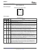
PACKAGE MATERIALS INFORMATION www.ti.com 19-Mar-2008 TAPE AND REEL INFORMATION *All dimensions are nominal Device UCC28019DR Package Package Pins Type Drawing SOIC D 8 SPQ Reel Reel Diameter Width (mm) W1 (mm) 2500 330.0 12.4 Pack Materials-Page 1 A0 (mm) B0 (mm) K0 (mm) P1 (mm) 6.4 5.2 2.1 8.0 W Pin1 (mm) Quadrant 12.
PACKAGE MATERIALS INFORMATION www.ti.com 19-Mar-2008 *All dimensions are nominal Device Package Type Package Drawing Pins SPQ Length (mm) Width (mm) Height (mm) UCC28019DR SOIC D 8 2500 340.5 338.1 20.
IMPORTANT NOTICE Texas Instruments Incorporated and its subsidiaries (TI) reserve the right to make corrections, enhancements, improvements and other changes to its semiconductor products and services per JESD46, latest issue, and to discontinue any product or service per JESD48, latest issue. Buyers should obtain the latest relevant information before placing orders and should verify that such information is current and complete.