
Interleaved PFC Pre-Requlator User's Guide

6.1 Output Ripple Voltage at Full Load
6.2 Input Ripple Current Cancellation
www.ti.com
Typical Performance Data
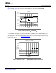
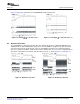
Figure 8 illustrates the output ripple voltage.
Figure 8. V
OUT
Ripple, P
OUT
= 300 W
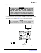
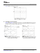
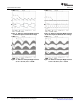
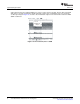
Figure 9 through Figure 14 show the input current (M
1
= I
L1
+ I
L2
), Inductor Ripple Current (I
L1
, I
L2
) versus
rectified line voltage. From these graphs, it can be observed that interleaving reduces the magnitude of
input ripple current caused by the inductor ripple current.
Figure 9. Inductor and Input Ripple Current at Figure 10. Inductor and Input Ripple Current
85 V
RMS
at Peak of Line Voltage at 85 V
RMS
Input at Half the Line Voltage
SLUU280B – May 2007 – Revised July 2008 UCC28060EVM 300-W Interleaved PFC Pre-Regulator 7
Submit Documentation Feedback