
Datasheet

SLUS517C − DECEMBER 2002 − REVISED SEPTEMBER 2005
6
www.ti.com
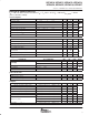
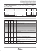
ELECTRICAL CHARACTERISTICS
T
A
= –40°C to 105°C for the UCC2851x, T
A
= T
J
, VCC = 12 V, R
T
= 156 kΩ, R
CT_BUFF
= 10 kΩ
(unless otherwise noted)
zero power
PARAMETER TEST CONDITIONS MIN TYP MAX UNITS
Zero power comparator threshold Measured on VAOUT, falling edge 0.20 0.33 0.50 V
Zero power comparator hysteresis Measured on VAOUT, rising edge 40 90 140 mV
PFC gate driver
PARAMETER TEST CONDITIONS MIN TYP MAX UNITS
GT1 pull-up resistance −100 mA ≤ ∆I
OUT
≤ −200 mA 5 12
Ω
GT1 pull-down resistance I
OUT
= 100 mA 2 10
Ω
GT1 output rise time
C
LOAD
= 1 nF, R
LOAD
= 10 Ω
16 25
ns
GT1 output fall time
C
LOAD
= 1 nF, R
LOAD
= 10 Ω
7 15
ns
Maximum duty cycle 93% 95% 100%
Minimum controllable pulse width 120 150 200 ns
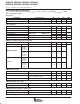
PWM stage undervoltage lockout (UVLO2)
PARAMETER TEST CONDITIONS MIN TYP MAX UNITS
PWM turn-on reference UCC2851X 6.30 6.75 7.30
PWM turn-off threshold
UCC28510
UCC28511
UCC28514
UCC28515
5.3
PWM turn-off threshold
UCC28512
UCC28513
UCC28516
UCC28517
3.55
V
Hysteresis
UCC28510
UCC28511
UCC28514
UCC28515
1.16 1.45 1.74
V
Hysteresis
UCC28512
UCC28513
UCC28516
UCC28517
2.56 3.20 3.84
PWM stage soft-start
PARAMETER TEST CONDITIONS MIN TYP MAX UNITS
SS2 charge current V
SENSE
= 7.5 V, SS2 = 0 V –7.0 –10.5 –14.0 µA
SS2 discharge current
V
SENSE
= 2.5 V, SS2 = 2.5 V,
(UVLO2 = Low, ENABLE = High)
6 10 14 mA
Input voltage (VERR) I
VERR
= 2 mA,UVLO2 = Low 300 mV
PWM stage duty cycle clamp
PARAMETER TEST CONDITIONS MIN TYP MAX UNITS
Maximum duty cycle D_MAX = 4.15 V 70% 75% 80%
PWM stage pulse-by-pulse current sense
PARAMETER TEST CONDITIONS MIN TYP MAX UNITS
Current sense comparator offset voltage I
SENSE2
= 0 V, measured on VERR 1.35 1.50 1.65 V
1. Ensured by design. Not 100% tested in production.