
Datasheet

UCC28600
SLUS646J –NOVEMBER 2005– REVISED JULY 2011
www.ti.com
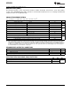
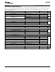
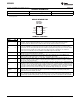
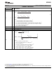
ELECTRICAL CHARACTERISTICS (continued)
VDD = 15 V, 0.1-μF capacitor from VDD to GND, 3.3-nF capacitor from SS to GND charged over 3.5 V, 500-Ω resistor from
OVP to -0.1 V, FB = 4.8 V, STATUS = not connected, 1-nF capacitor from OUT to GND, CS = GND, T
A
= -40°C to 105°C,
(unless otherwise noted)
PARAMETER TEST CONDITIONS MIN TYP MAX UNIT
Current Sense (CS)
(2)
A
CS(FB)
Gain, FB = ΔV
FB
/ ΔV
CS
QR mode 2.5 V/V
Shutdown threshold V
FB
= 2.4 V, V
SS
= 0 V 1.13 1.25 1.38 V
CS to output delay time (power limit) CS = 1.0 V
PULSE
100 175 300
ns
CS to output delay time (over current
CS = 1.45 V
PULSE
50 100 150
fault)
CS discharge impedance CS = 0.1 V, V
SS
= 0 V 25 115 250 Ω
V
CS(os)
CS offset SS mode, V
SS
≤ 2.0 V, via FB 0.35 0.40 0.45 V
Power Limit (PL)
(2)
I
PL(cs)
CS current OVP = -300 μA -165 -150 -135 μA
CS working range QR mode, peak CS voltage 0.70 0.81 0.92
V
V
PL
PL threshold Peak CS voltage + CS offset 1.05 1.20 1.37
Soft Start (SS)
I
SS(chg)
Softstart charge current V
SS
= GND -8.3 -6.0 -4.5 μA
I
SS(dis)
Softstart discharge current V
SS
= 0.5 V 2.0 5.0 10 mA
V
SS
Switching ON threshold Output switching start 0.8 1.0 1.2 V
Overvoltage Protection (OVP)
I
OVP(line)
Line overvoltage protection I
OVP
threshold, OUT = HI -512 -450 -370 μA
V
FB
= 4.8 V, V
SS
= 5.0 V, I
OVP(on)
, = -300
V
OVP(on)
OVP voltage at OUT = HIGH -125 -25 mV
μA
V
OVP(load)
Load overvoltage protection V
OVP
threshold, OUT = LO 3.37 3.75 4.13 V
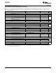
Thermal Protection (TSP)
Thermal shutdown (TSP) temperature
(3)
130 140 150
°C
Thermal shutdown hysteresis 15
OUT
t
RISE
Rise time 10% to 90% of 13 V typical out clamp 50 75
ns
t
FALL
Fall time 10 20
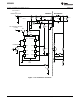
(2) R
SCT
and C
CST
are not connected in the circuit for maximum and minimum duty cycle tests, current sense tests and power limit tests.
(3) Ensured by design. Not production tested.
4 Copyright © 2005–2011, Texas Instruments Incorporated