
Datasheet


SLUS274A – JANUARY 1999 – REVISED APRIL 2003
1
www.ti.com
FEATURES
D
Precision Fault Threshold
D Programmable Average Power Limiting
D Programmable Linear Current Control
D Programmable Overcurrent Limit
D Programmable Fault Time
D Fault Output Indicator
D Shutdown Control
D Undervoltage Lockout
D 8-Pin SOIC
APPLICATIONS
D
–48-V Distributed Power Systems
D Central Office Switching
D Wireless Base Stations
DESCRIPTION
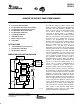
The UCCx913 family of negative voltage circuit
breakers provides complete power management,
hot-swap, and fault handling capability. The
device is referenced to the negative input voltage
and is driven through an external resistor
connected to ground, which is essentially a
current drive as opposed to the traditional voltage
drive. The on-board 10-V shunt regulator protects
the device from excess voltage and serves as a
reference for programming the maximum
allowable output sourcing current during a fault. In
the event of a constant fault, the internal timer
limits the on-time from less than 0.1% to a
maximum of 3%. The duty cycle modulates
depending on the current into the PL pin, which is
a function of the voltage across the FET, and limits
average power dissipation in the FET. The fault
level is fixed at 50 mV across the current-sense
resistor to minimize total dropout. The fault current
level is set with an external current sense resistor.
The maximum allowable sourcing current is
programmed with a voltage divider from VDD to
generate a fixed voltage on the IMAX pin. The
current level, when the output appears as a
current source, is equal to V
IMAX
/R
SENSE
. If
desired, a controlled current startup can be
programmed with a capacitor on the IMAX pin.
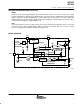
When the output current is below the fault level,
the output device is switched on. When the output
current exceeds the fault level, but is less than the
maximum sourcing level programmed by the
IMAX pin, the output remains switched on, and the
fault timer starts charging CT. Once CT charges to
2.5 V, the output device is turned off and performs
a retry some time later. When the output current
reaches the maximum sourcing current level, the
output appears as a current source, limiting the
output current to the set value defined by IMAX.
Other features of the UCCx913 family include
undervoltage lockout, and 8-pin small outline
(SOIC) and dual-in-line (DIP) packages.
Copyright 1999 – 2003, Texas Instruments Incorporated
1
8
7
6
5
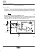
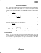
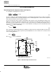
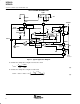
–VIN
3
UCC3913
2
4
Power
Limiting
Current
Control
Fault
Protection
and
Timer
DC/DC
Converter
or Load
R
VDD
SIMPLIFIED APPLICATION DIAGRAM
R
S
R1
R2
R
PL
C
T
C
VDD
M1
UDG–03059